An adaptive analytical ray-tracing code to study black hole photon rings
Project description
Adaptive Analytical Ray Tracing (AART)
AART is a numerical framework that exploits the integrability properties of Kerr spacetime to compute high-resolution black hole images and their visibility amplitude on long interferometric baselines. It implements a non-uniform adaptive grid in the image plane suitable to study black hole photon rings (narrow ring-shaped features predicted by general relativity but not yet observed).
The code, described in detail in Ref. [1], implements all the relevant equations required to compute the appearance of equatorial sources on the (far) observer's screen. We refer the reader to Refs. [2-4] for derivations and further details. Through the code, the equations are mentioned as Pi Eq. N, which means Eq. N in Ref. [i].
Please refer to the AART homepage found under the "Project links" header for an example Jupyter notebook in which use of the AART package is illustrated.
The use of AART in scientific publications must be properly acknowledged. Please cite:
Cardenas-Avendano, A., Lupsasca, A. & Zhu, H. "Adaptive Analytical Ray Tracing of Black Hole Photon Rings." arXiv:2211.07469
We also request that AART modifications or extensions leading to a scientific publication be made public as free software.
Feel free to use images and movies produced with this code (with attribution) for your next presentation!
Last updated: 08.24.2023
AART's Components
-
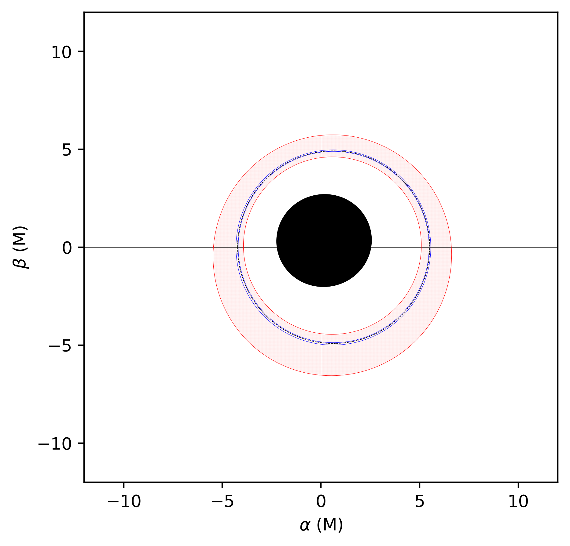
Lensing Bands: the functions are located in lensingbands.py. This module computes Bardeen's coordinates inside the so-called lensing bands. Currently it only computes $0\le n\le 2$, but extension to a higher $n$ is possible: just copy the structure of the code and add the desired number $n$ on a Cartesian grid with different resolutions.
-
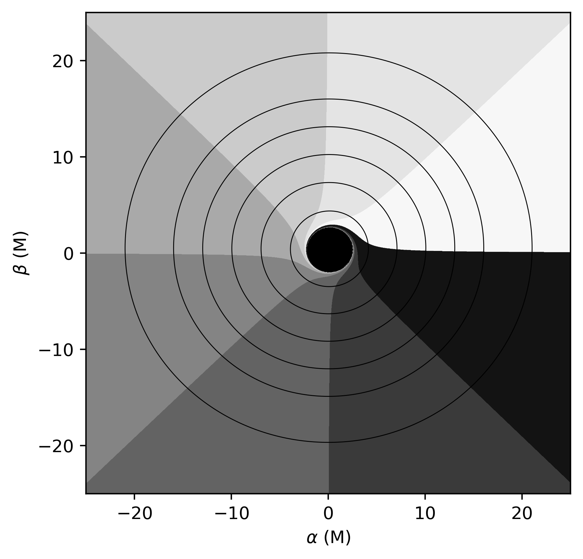
Analytical Ray-Tracing: the main functions are located in raytracing_f, while the master function is located in raytracing.py. For a given location in Bardeen's plane ($\alpha,\beta$), it computes where it lands in the equatorial plane ($t,r,\theta=\pi/2,\phi$) in Boyer-Lindquist coordinates. The implementation does this per lensing band.
-
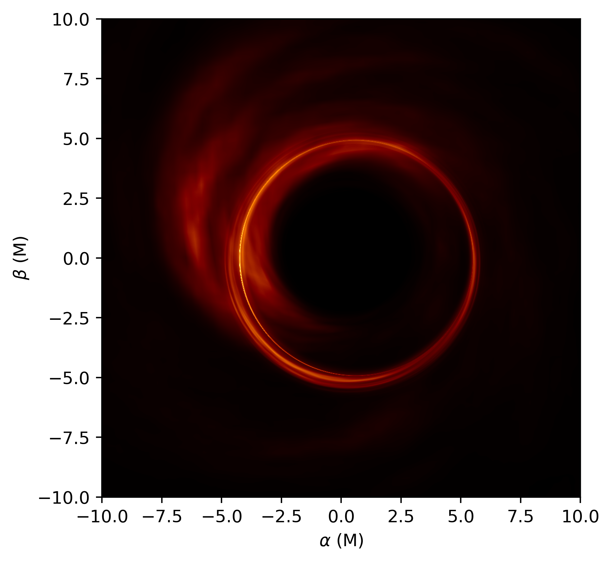
Images: the source functions are located in iImages.py. It computes an image for a given analytical illumination profile specified in its arguments, if it is purely radial and analytical, or as an external file. The current version of the code supports inoisy (https://arxiv.org/abs/2011.07151) outputs, where the external file is an HDF5 with a specific structure. Below you can find a low-resolution example.
-
Visibility Amplitudes: the main functions are located in visamp_f.py, while the master function is located in visamp.py. It computes the visibility amplitudes for given intensities over $n$ lensing bands.
-
Polarization: the main functions are located in polarization_f.py, while the master function is located in polarization.py. For a given magnetic field configuration specified in the arguments, it parallel transports the linear polarization of a photon.
Dependencies
Python Libraries:
All the dependencies are located in the init.py file. Most of the libraries will come natively with anaconda (e.g., numpy, scipy >=1.8, matplotlib, multiprocessing, skimage) but some may not.
To install any missing packages, run
pip install "package_name"
or, if using anaconda, search for the missing packages and run, e.g. for h5py (read and write HDF5 files from Python),
conda install -c anaconda h5py
Sometimes scipy does not automatically update to the latest version. If that is the case, you should run
pip install -U scipy
How to run AART
The parameters are set in the individual functions.
We present some examples in the notebook Examples.ipynb.
Lensing Bands:
The lensing bands are computed by running
python aart.lensingbands.clb(spins, angles)
where spins, and angles are arrays. For example, spins=[0.5, 0.6], and angles=[17, 50] would result in the calculation of the lensing bands for the four spin-angle combinations (a, i): (0.5, 17), (0.5, 50), (0.6, 17), and (0.6, 50).
The result of the lensingbands function will be stored in a HDF5 file that contains the values of the Bardeen's coordinates within each lensing band. The datasets inside the resulting file are:
-
alpha: the coordinate alpha of the critical curve. The parameter npointsS controls the number of points used for the computation of the critical curve)
-
beta: The coordinate beta of the critical curve
-
hull_ni: the points for the inner convex hull of the $n$th band. Note that hull_0i corresponds to the location of the apparent horizon. hull_ne: the points for the outer convex hull of the $n$th band. Note that hull_0e corresponds to edges of the domain.
-
gridn: the point within the $n$th lensing band
-
Nn: number of points within the $n$th lensing band
-
limn: the grids are cartesian and symmetric around zero. This dataset indicates the limits of the grid.
This image is produced in the example code:
Note that there are more arguments in the lensingbands function. These can be identified by running
import inspect
inspect.getfullargspec(aart.lensingbands.clb)
which will print out all the arguments that the function lensingbands takes. In the rest of the readme the full range of arguments that each function takes will not be listed; the above code can be run for any of the functions to find the range of arguments, while their descriptions can be found in the respective python files for the so-called master functions.
Ray Tracing:
To compute the equatorial radius, angle, and emission time of a photon, we perform a backward ray-tracing from the observer plane. By running the following, we evaluate the source radius, angle, and time within the grid from each lensing band:
python aart.raytracing.raytrace(spins, angles)
The result will be stored in a HDF5 file that contains source radius, angle, time, as well as the radial component of the four momentum in the equatorial plane, for lensing bands n=0,1,2. The datasets inside the resulting file are:
- rsn: the value of the $r$ Boyer-Lindquist coordinate for the $n$th lensing band. It follows the order of the lensing band
- tn: the value of the $t$ Boyer-Lindquist coordinate for the $n$th lensing band. It follows the order of the lensing band
- phin: the value of the $\phi$ Boyer-Lindquist coordinate for the $n$th lensing band. It follows the order of the lensing band
- signn: the sign of the radial momentum of the emitted photon in the $n$th lensing band.
This image is produced in the example code:
Images:
Stationary and axisymmetric source profiles:
Once the lensing bands and the rays have been computed, an image can be produced using a specified analytical profile by running
def mu_p(spin_case):
    return 1-np.sqrt(1-spin_case**2)

python aart.radialintensity.cintensity(spins, angles, mu_p=mu_p, gammap=-3/2, sigmap=1/2, gfactor=3.0)
where mu_p, gammap, and sigmap specify the analytical profile in according to Johnson’s SU distribution and we've chosen specific values as an illustration.
The datasets inside the resulting file are:
- bghtsn: the intensity at each point in the image.
This image is produced in the example code:
Non-stationary and non-axisymmetric source profiles:
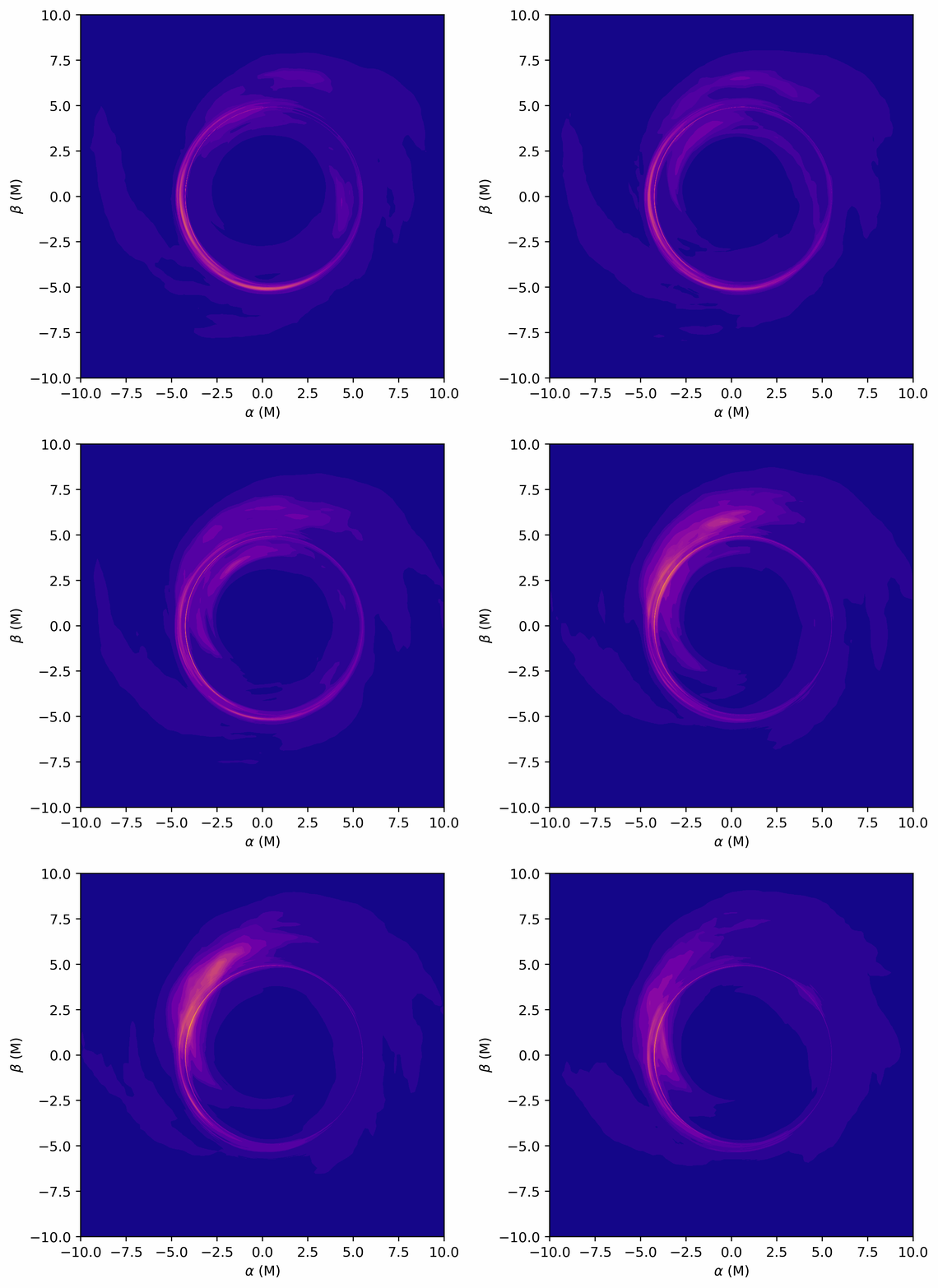
As the dataset produced after ray tracing contains all the information of the BL coordinates, one can also use analytical non-stationary and non-axisymmetric source profiles to produce images (that use the entire history of the profile) and movies.
One can also use a precomputed equatorial profile. AART currently implements profiles computed with inoisy. The example includes a test case (inoisy.h5), for which one can run
python aart.iImages.image(spins, angles)
or
python aart.iMovies.movie(spins, angles)
to produce an image or a set of images, respectively. Images can be produced by using a single equatorial profile, i.e., in the mode "stationary," or using the entire history of the equatorial structure, i.e, in the mode "dynamical." When movies are made, the dynamical version is assumed. In both cases, the resulting datasets inside the resulting file are:
- bghtsn: the intensity at each point in the image. When several snapshots are produced, these datasets will have three dimensions, where the first one denotes the time.
This gif is produced in the example code:
Visibility Amplitudes:
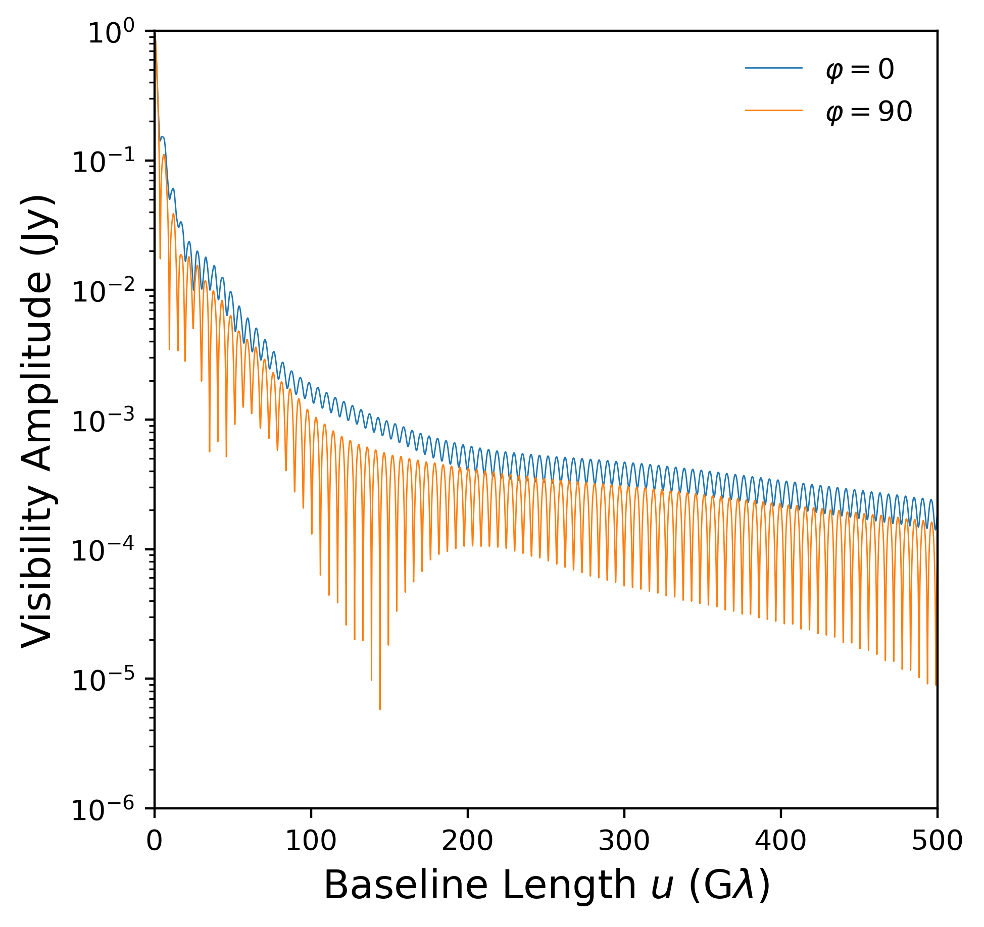
With the images created using radial intensity profiles, one may then calculate the visibility of the image projected onto a baseline by running
python aart.visamp.cvisamp(spins, angles, radonangles=radonangles)
This function first performs radon transforms of the image at a set of specified angles (the radonangles argument in some of the above functions), and then computes the visibility amplitude. The output is a set of h5 files, one for each baseline angle. These files contain the visibility amplitude as well as the frequency (baseline length in G$\lambda$). The resulting datasets inside the resulting file are:
- freqs: the frequencies over which the visibility amplitudes were computed
- visamp: the respective visbility amplitudes.
If in the function cvisamp the argument radonfile=1, the HD5F file will also contain these two datasets:
- radon: the resulting radon transformation
- x_radon: the axis values of the projection.
This image is produced in the example code:
Polarization:
The linear polarization of a given configuration of the magnetic field can be computed by running
python aart.polarization.polarization.(spins, angles)
The resulting datasets inside the resulting file are:
- PK: the Walker-Penrose constant
- EVPA_x: the x-component of the the electric-vector position angle
- EVPA_y: the y-component of the the electric-vector position angle.
Limitations and known possible performance bottlenecks
-
This code has only been tested on Mac OS (M1 and Intel) and on Ubuntu.
-
If you want to run a retrograde disk, you will have to apply symmetry arguments. In other words, run the positive spin case ($-a$), flip the resulting lensing bands and rays, and then compute the intensity on each pixel. Note that the characteristic radii also need to be modified. We plan to add this feature in a future version.
-
The radon cut does not smoothly go to zero. This is sometimes clear from the visamp, where you can see an extra periodicity (wiggle) on each local maxima. To solve this issue, increase the FOV of the $n=0$ image by providing a larger value for the argument limits in the relevant functions. You can also modify the percentage of points used in npointsfit in visamp_f.py.
-
Producing the lensing bands can take too long, in particular, for some larger inclination values computing the contours of the lensing bands and the points within it takes a long time. The calculation can be made faster at the cost of some accuracy if you decrease the number of points used to compute the contours, i.e., by decreasing the value of the argument npointsS. It is faster to compute the convex hull instead of the concave hull (alpha shape), but then you will have to check that you are not missing points (having extra points is not an issue with the analytical formulae, as the results are masked out). If using the convex hull is acceptable, then you can also change the function in_hull in lensingbands.py to use hull.find_simplex instead of contains_points.
Authors
- Alejandro Cardenas-Avendano (cardenas-avendano@princeton.edu)
- Hengrui Zhu
- Alex Lupsasca
- Lennox Keeble (python package creation and maintenance)
References
[1] Cardenas-Avendano, A., Lupsasca, A. & Zhu, H. Adaptive Analytical Ray Tracing of Black Hole Photon Rings. arXiv:2211.07469
[2] Gralla, S. E., & Lupsasca, A. (2020). Lensing by Kerr black holes. Physical Review D, 101(4), 044031.
[3] Gralla, S. E., & Lupsasca, A. (2020). Null geodesics of the Kerr exterior. Physical Review D, 101(4), 044032.
[4] Gralla, S. E., Lupsasca, A., & Marrone, D. P. (2020). The shape of the black hole photon ring: A precise test of strong-field general relativity. Physical Review D, 102(12), 124004.
MIT License
Permission is hereby granted, free of charge, to any person obtaining a copy of this software and associated documentation files (the "Software"), to deal in the Software without restriction, including without limitation the rights to use, copy, modify, merge, publish, distribute, sublicense, and/or sell copies of the Software, and to permit persons to whom the Software is furnished to do so, subject to the following conditions:
The above copyright notice and this permission notice shall be included in all copies or substantial portions of the Software.
THE SOFTWARE IS PROVIDED "AS IS", WITHOUT WARRANTY OF ANY KIND, EXPRESS OR IMPLIED, INCLUDING BUT NOT LIMITED TO THE WARRANTIES OF MERCHANTABILITY, FITNESS FOR A PARTICULAR PURPOSE AND NONINFRINGEMENT. IN NO EVENT SHALL THE AUTHORS OR COPYRIGHT HOLDERS BE LIABLE FOR ANY CLAIM, DAMAGES OR OTHER LIABILITY, WHETHER IN AN ACTION OF CONTRACT, TORT OR OTHERWISE, ARISING FROM, OUT OF OR IN CONNECTION WITH THE SOFTWARE OR THE USE OR OTHER DEALINGS IN THE SOFTWARE.
Project details
Release history Release notifications | RSS feed
Download files
Download the file for your platform. If you're not sure which to choose, learn more about installing packages.


