cocotbext-ospi
OSPI flash verification for cocotb: a bus driver, a device-level API over the JEDEC command set, and a NOR flash model to test against — single, dual, quad and octal I/O.
Requires cocotb 2.0+. Tests run on Icarus Verilog.
pip install cocotbext-ospi
Why another SPI extension
cocotbext-spi covers
single-lane SPI. This one covers flash specifically, up to an eight-lane
data bus, with the write-enable latch, status polling, page program and
sector erase — and it targets cocotb 2.x.
Pointing a testbench at the models
The Verilog ships inside the package, so there is nothing to vendor. Ask the package where it is:
VERILOG_DIR := $(shell python3 -c \
    "import cocotbext.ospi as o; print(o.verilog_dir())")

VERILOG_SOURCES  = $(VERILOG_DIR)/devices/mx25um51345g.v
VERILOG_SOURCES += $(VERILOG_DIR)/devices/mx25um51345g_test.v
COMPILE_ARGS    += -I$(VERILOG_DIR)/devices
Or from Python, cocotbext.ospi.verilog_dir() returns a pathlib.Path.
Usage
import cocotb
from cocotb.clock import Clock
from cocotbext.ospi import OspiFlash, CMD_OIOR

@cocotb.test()
async def test_flash(dut):
    cocotb.start_soon(Clock(dut.clk, 20, unit="ns").start())

    flash = OspiFlash(dut)
    await flash.initialize()

    assert await flash.read_id() == [0xC2, 0x80, 0x39]

    # program() sets WEL, then polls the status register until WIP clears.
    await flash.program(0x1000, [0xDE, 0xAD, 0xBE, 0xEF])

    assert await flash.read(0x1000, 4) == [0xDE, 0xAD, 0xBE, 0xEF]
    assert await flash.read(0x1000, 4, opcode=CMD_OIOR) == [0xDE, 0xAD, 0xBE, 0xEF]

    await flash.erase_sector(0x1000)
    assert await flash.read(0x1000, 4) == [0xFF] * 4
The protocol, and two things that catch people out
SPI mode 0: the master launches data while the clock is low, the device samples it on the rising edge, and vice versa.
How wide the opcode is depends on the protocol, and this trips people up.
The names say it: in 1-4-4 — a quad read issued to a part still in
ordinary SPI — the leading 1 means the opcode goes out on one lane and only
the address and data widen. In 8-8-8 the part has been switched into
octal wholesale, so the opcode is eight lanes too, and it comes as a pair
with its extension byte.
Mixing these up is the most common reason a controller talks to nothing, and
it is why xspi_controller takes a separate lane count for the command
phase rather than assuming either. (The sibling cocotbext-qspi is the
1-4-4 case throughout, so there the opcode really is always single-lane.)
Programming only clears bits. NOR flash needs an erase to set a bit back
to 1. Programming 0x0F over 0xF0 gives 0x00, not 0x0F.
What it looks like on the wire
All three diagrams below are generated from a real simulation — capture.py
runs the transactions, Icarus dumps a VCD, and render.py draws it. Nothing
is drawn by hand, so they cannot drift away from what the model does.
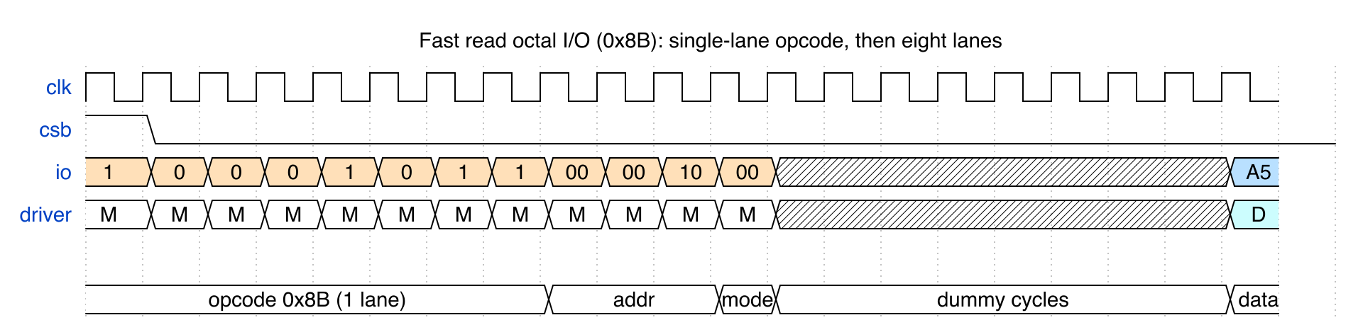
An octal I/O read. The opcode goes out one bit per clock on a single lane; only then does the bus widen to all eight for the address and data — a whole byte per clock. Note the dummy cycles, where neither side drives while the bus turns around:
The same byte read at every width. This is what the wide modes buy you — 40 clocks single-lane down to 21 octal, for one byte at the same address:

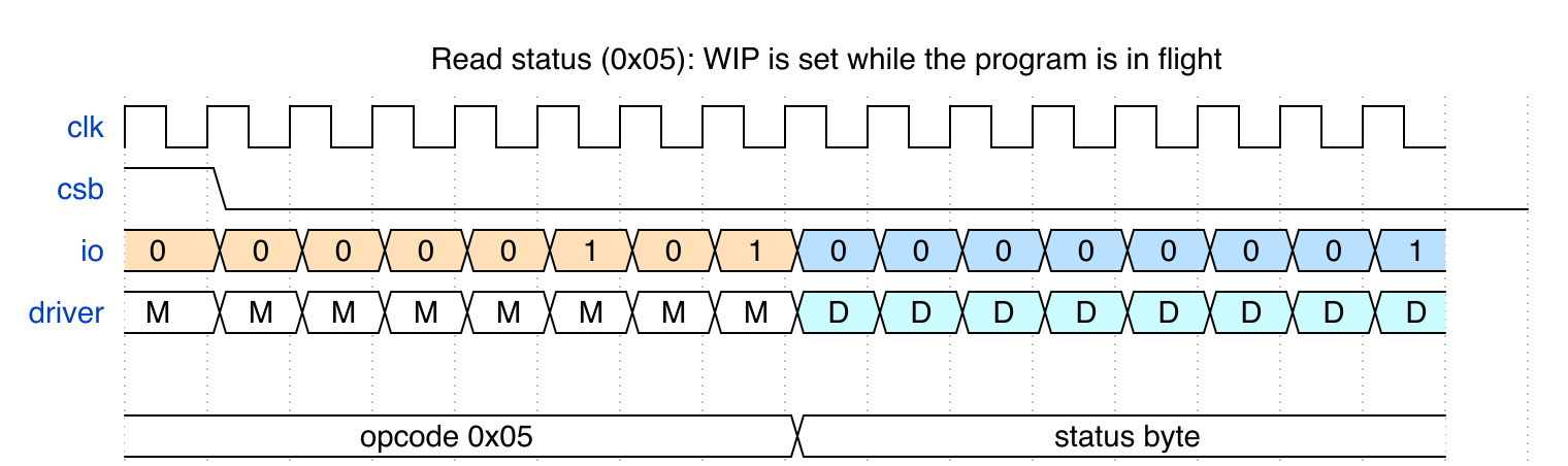
A status read while a program is in flight. The device answers 0x01 — WIP
set — which is what wait_ready() polls for:
To regenerate them:
make -C docs/waveforms        # run the sim, dump capture.vcd
make -C docs/waveforms svg    # capture.vcd -> *.svg
Commands
| Opcode | Name | Address | Data |
|---|---|---|---|
0x06 |
Write enable | — | — |
0x04 |
Write disable | — | — |
0x05 |
Read status | — | 1 lane, repeats |
0x9F |
JEDEC id | — | 1 lane, 3 bytes |
0x03 |
Read | 1 lane | 1 lane |
0xBB |
Fast read dual I/O | 2 lanes | 2 lanes, after mode byte + dummy |
0xEB |
Fast read quad I/O | 4 lanes | 4 lanes, after mode byte + dummy |
0x8B |
Fast read octal I/O | 8 lanes | 8 lanes, after mode byte + dummy |
0x02 |
Page program | 1 lane | 1 lane; needs WEL, sets WIP |
0x20 |
Sector erase (4 KB) | 1 lane | — ; needs WEL, sets WIP |
Status register: bit 0 WIP (write in progress), bit 1 WEL (write enable
latch). wait_ready() polls it rather than assuming a fixed delay, which is
what a real controller must do.
HOLD_N is active low: high is normal operation, and pulling it low
freezes the interface mid-transaction without losing state.
Real device models
Alongside the generic model there are models of specific parts, built from
their datasheets and cross-checked against Linux's drivers/mtd/spi-nor:
| Part | Protocols | Command extension | Octal entry |
|---|---|---|---|
| Macronix MX25UM51345G | 1S-1S-1S, 8S-8S-8S, 8D-8D-8D | inverted (~opcode) |
CR2 0x00000000 |
| Micron MT35XU512ABA | 1S-1S-1S, 8D-8D-8D | repeated (opcode) |
CFR1V then CFR0V |
from cocotbext.ospi.devices import MX25UM51345G
from cocotbext.ospi.xspi_flash import XspiFlash

flash = XspiFlash(dut, MX25UM51345G)
await flash.initialize()                       # the part boots single-lane
assert await flash.read_id() == [0xC2, 0x81, 0x3A]

await flash.enter_octal()                      # writes CR2, switches protocol
assert await flash.read_id() == [0xC2, 0x81, 0x3A]   # now over eight lanes
Three things real parts do that a generic octal model does not
Octal commands come in pairs. In 8-8-8 the opcode goes out eight lanes
wide, immediately followed by an extension byte. Macronix sends the
bitwise complement (8READ is EC/13), Micron repeats the opcode. Linux
calls these SPI_NOR_EXT_INVERT and SPI_NOR_EXT_REPEAT. Send the wrong
one and the model rejects the command — the two disagree about this
deliberately, and each has a test proving it refuses the other's form.
That rejection is a modelling choice, flagged as such in both models. The datasheets and Linux say what a controller must send; neither says what silicon does with a mismatched extension. Refusing it is what turns a controller configured for the wrong vendor into an obvious failure instead of undefined behaviour.
Commands change shape with the protocol. RDSR takes no address and no
dummy cycles in SPI, but on the Macronix part in OPI it grows a 4-byte
address and four dummy cycles. RDID likewise. Addresses are 4 bytes, not
3.
Dummy cycles are configurable and you must track them. DC[2:0] in
Macronix CR2 0x300 selects 20/18/16/14/12/10/8/6 cycles depending on clock
frequency; Micron's CFR1V holds the count directly. A controller that does
not follow the register reads garbage — there is a test that walks the whole
table.
8D-8D-8D
Both parts run at double transfer rate: a bit per lane on both clock edges, so eight lanes move two bytes per clock. That is why an odd number of bytes cannot be transferred in that mode, and why leaving it means writing CFR0V and CFR1V together in one 2-byte write — which is exactly what Linux does.
Macronix has separate STR and DTR octal reads (8READ = EC/13,
8DTRD = EE/11) selected by CR2 bit 0 or bit 1; enter_octal() takes
the protocol you want. Its DTR mode also enforces datasheet note 5: the
start address must be even. An odd one is rejected rather than quietly
returning the neighbouring byte.
The DTR edge handling is validated against PicoSoC's spiflash.v quad-DTR
read (0xED), an independently written model, for the same reason the rest
of the interop suite exists.
DQS
A separate pin, not part of SIO[7:0]. The device strobes it alongside read
data so a controller can capture with the data rather than with its own
clock, which is what makes high-speed DTR reads timing-closable.
The shape is taken from the Rev 1.3 timing figures, read from the artwork —
the text extraction carries only bare DQS row labels:
| Phase | DQS |
|---|---|
| Command, extension, address | held high |
| Dummy | low |
| Data | toggles with the clock |
It is not parked low while busy, which matters to a controller that gates on it: DQS low means dummy-or-idle, not idle alone. Getting this backwards is exactly the sort of thing a model tested only against its own driver never notices — the tests would assert whatever the model did.
DTR always strobes. STR only does so if DOS (CR2 0x200 bit 1) asks, and
a controller that enables DQS capture without setting it waits for edges
that never come.
Two things the datasheet does not settle, flagged in the model and pinned by tests so the choices are visible:
- Only one STR-OPI figure carries a DQS row at all — the array read.
Every STR-OPI register read is drawn without one, so whether
DOSmakesRDSRorRDIDstrobe is undocumented. The model says yes. - No figure shows DQS after the final data byte, so returning low at the end of a burst is an assumption.
SFDP
Both models carry a real SFDP image, so a driver can discover a part instead of being told about it:
info = await flash.discover()
info.size_bytes          # 67108864  (512 Mb)
info.address_bytes_name  # '4 only'
info.dtr                 # True
info.page_size           # 256
info.erase_types         # [(4096, 0x21), (65536, 0xDC)]
RDSFDP (0x5A) changes shape with the protocol — 3 address bytes and 8
dummy cycles in SPI, 4 and 20 in OPI — so discovery has to know which mode
it is in. Both profiles carry both shapes, and a test reads the same table
each way.
Both parts also carry an xSPI Profile 1.0 table (JESD251, id 0xFF05),
which is how a part advertises its octal DTR capability rather than being
told: the fast-read opcode, the dummy cycles needed at each frequency, and
the shape RDSR takes in octal.
info = await flash.configure_from_sfdp(mhz=200)
# reads Profile 1.0 and points the driver's octal read at the advertised
# opcode and dummy count -- no profile constants involved
That the two parts disagree here is the point: Macronix RDSR takes a
4-byte address and 4 dummy cycles in octal, Micron's takes none and 8. A
controller hardcoded for one misreads the other, which is what Profile 1.0
exists to prevent. Each part has a test asserting its own shape and the
other's.
The tests also check the table is not lying: every advertised dummy count is programmed into CR2 and the read has to still work.
The tables are built by cocotbext/ospi/sfdp.py and emitted into the models
by cocotbext/ospi/verilog/devices/generate_sfdp.py. Defining them once and generating the
Verilog is what stops the model and the parser drifting apart — and the
tests read back through the parser exactly what the generator put in.
python3 cocotbext/ospi/verilog/devices/generate_sfdp.py # regenerate the ROMs
Reset
initialize() issues the RSTEN/RST pair. A part left in octal by a
previous run cannot understand a single-lane command, so the sequence is
sent in every protocol the profile supports; the one the part is actually in
takes effect and the rest are ignored as malformed. Without this, tests
quietly depend on whatever mode the previous one left behind.
What is not modelled
Micron's suspend/resume and its lock registers; Macronix's SPB and lock
register (the volatile DPB layer is modelled, the non-volatile one is not);
ECC and CRC; the secured OTP array; and SFDP tables beyond BFPT, Profile 1.0
and 4BAIT. Timing parameters are simulation-convenient rather than
datasheet-accurate — PROGRAM_NS and ERASE_NS are parameters, not the
real tPP/tSE.
The arrays are a small window rather than the full 64 MB so simulations stay fast; capacity is reported honestly in both the JEDEC ID and SFDP.
make -C tests -f Makefile.mx25          # Macronix, 38 tests
make -C tests -f Makefile.mt35          # Micron, 24 tests
make -C tests -f Makefile.controller    # controller DUT, 8 tests
A controller as DUT
Everything above points a driver at a flash model. cocotbext/ospi/verilog/controller/
inverts that: an xspi_controller is the RTL under test, driving the
MX25UM51345G model, with cocotb poking only its command interface. It never
touches the flash pins — if the controller gets a phase wrong, the bytes come
back wrong and nothing in Python can paper over it.
make -C tests -f Makefile.controller # 8 tests
One command per handshake: opcode, optional extension byte, address, address width, dummy cycles, lane counts, direction and length. Nothing in it is specific to a particular flash, so the same RTL drives the part in single-lane SPI and in octal.
It is deliberately small — a sequencer, not a product. What it is for is being something real to point the models at, and it earned that immediately: writing it exposed an opcode-width error in this README, because the driver and the model both happened to be right while the prose was wrong. A closed loop of our own components could not have surfaced that.
Single transfer rate only. DTR needs data on both edges and two sample
points per period, and the counters step once per sclk period, so it is a
real change rather than a parameter.
Bus signals
OspiBus.from_entity(dut) picks up clk, csb, io and HOLD_N, plus
io_out and io_oe.
A simulator will not let a testbench drive an inout net, so the top level
splits the master's half into a value and a per-lane output enable:
wire [7:0] io;
genvar g;
generate
    for (g = 0; g < 8; g = g + 1) begin : lane
        assign io[g] = io_oe[g] ? io_out[g] : 1'bz;
    end
endgenerate
Per-lane, not bus-wide: in single-lane mode the master drives io0 while
the device answers on io1.
Note also that csb is left uninitialised in ospi_flash_test.v. The model
frames transactions on chip-select edges, and an initialiser there races
cocotb's first write at time 0 — the edge is lost and the device never
starts. initialize() drives the sequence explicitly.
Testing
Two suites, and the split matters:
make -C tests                      # against our own JEDEC model: 12 tests
make -C tests -f Makefile.interop  # against PicoSoC's spiflash.v: 5 tests
The interop suite drives
spiflash.v — a model this project
did not write — and checks the bytes against known $readmemh content.
That distinction earned its keep. Testing only against our own model proves the driver and the model agree; it does not prove either is right. Driving somebody else's model immediately found that the master was dropping the first bit of every byte — our model had the same off-by-one assumption, so the closed loop had been happily agreeing with itself.
Scope of that check: spiflash.v is a four-lane part, so interop covers
the single, dual and quad paths. There is no comparable open-source octal
model, so the eight-lane path is exercised only against our own model. Treat
octal as less hardened than the rest.
Layout
| Path | Contents |
|---|---|
cocotbext/ospi/ospi_flash.py |
OspiFlash — JEDEC command set, status polling, hold |
cocotbext/ospi/ospi_master.py |
OspiMaster — byte transfers at 1/2/4/8 lanes |
cocotbext/ospi/ospi_bus.py |
OspiBus — signal bundle |
cocotbext/ospi/ospi_config.py |
OspiConfig, lanes_for_mode |
cocotbext/ospi/verilog/ospi_flash.v |
NOR flash model: WEL, WIP, page program, sector erase, hold |
cocotbext/ospi/verilog/ospi_flash_test.v |
cocotb top level |
tests/reference/ |
third-party model for interop (ISC, see its README) |
Licence
MIT. tests/reference/spiflash.v is ISC, © Claire Xenia Wolf.
1 maintainer

Metadata
1 maintainer
Release files for cocotbext-ospi 0.2.0
For a detailed explanation of source distributions (sdists) and built distributions (wheels), please see the package formats documentation.
Source distribution (sdist)
| File | Size | Uploaded | |
|---|---|---|---|
| cocotbext_ospi-0.2.0.tar.gz | 65.1 kB | Details |
Built distribution (wheel)
| File | Interpreter | ABI | Platform | Reset |
|---|---|---|---|---|
| cocotbext_ospi-0.2.0-py3-none-any.whl | Python 3 | none | any | Details |
Total release size: 120.4 kB
Release files / cocotbext_ospi-0.2.0.tar.gz
| Download URL | cocotbext_ospi-0.2.0.tar.gz |
|---|---|
| Size | 65.1 kB |
| Tags | Source |
|
SHA-256 checksum How to use checksums |
008c3915e2fc09de2e60b41ab7496627f0fd1eecb928da1e043024c9b550f380
|
|
BLAKE2b-256 checksum How to use checksums |
c16987fb6e0cbee246012b7a940c5f26f7f1f3b1915a668575e11c78f5b23629
|
| Upload date | |
|
Uploaded using Trusted Publishing? What is trusted publishing? |
Yes |
| Uploaded via |
twine/7.0.0 CPython/3.13.14
|
Provenance
Provenance describes where a file came from. On PyPI, provenance is shared via attestations, which provide a verifiable record of the build or publishing details. View details, limitations and caveats.


PyPI Publish Attestation
PyPI verified that this artifact, at this checksum, originated from the publisher listed below.
Signed by GitHub Actions, verified by PyPI on Sep 19, 2026.
Transparency logRelease files / cocotbext_ospi-0.2.0-py3-none-any.whl
| Download URL | cocotbext_ospi-0.2.0-py3-none-any.whl |
|---|---|
| Size | 55.3 kB |
| Tags | Python 3 |
|
SHA-256 checksum How to use checksums |
ea621143749494b0114b5d8b794862acdaebb3da46daab2132bb68f7eb8580b2
|
|
BLAKE2b-256 checksum How to use checksums |
69429944bde7ae8971af2525c6e33c16a18a88b128129374556be721b95b394d
|
| Upload date | |
|
Uploaded using Trusted Publishing? What is trusted publishing? |
Yes |
| Uploaded via |
twine/7.0.0 CPython/3.13.14
|
Provenance
Provenance describes where a file came from. On PyPI, provenance is shared via attestations, which provide a verifiable record of the build or publishing details. View details, limitations and caveats.
PyPI Publish Attestation
PyPI verified that this artifact, at this checksum, originated from the publisher listed below.
Signed by GitHub Actions, verified by PyPI on Sep 19, 2026.
Transparency log