Plugin to handle small LCD display - Through GPIO 4/8 bit mode or I2c.


Project description


pibooth-lcd-display is a plugin for the pibooth application.
Add any 16x2 or 20x4 LCD-screen with a Hitachi HD44780 controller using either a port expander connected through I2c or just wire through GPIO 4 or 8 bit.
We recommend using LCD-screen with I2c, as it uses less wire (only 4), is faster and more stable.
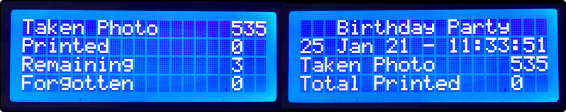
It can show numbers of Photos Taken, Printed Photos, Forgotten Photos, Remaining Duplicates.
It also have 4 x Free-Text where you can write your own text, and show Date/Time.
Examples:
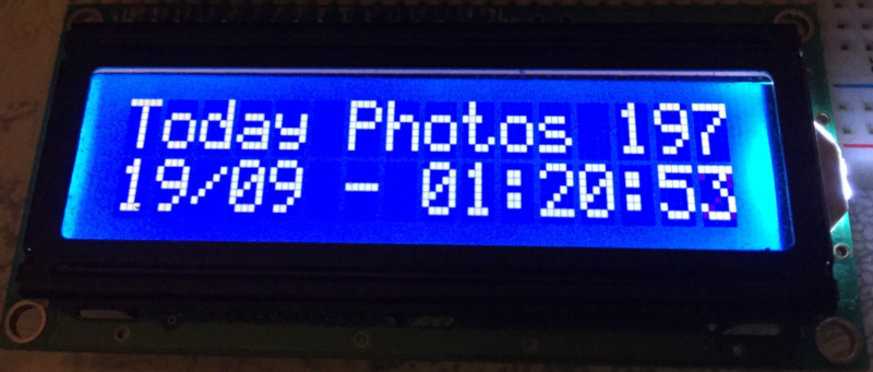
Show pibooth counters like “Taken Photos 197” or “Today Photos 197”
Show some free text in the line “Hello from pibooth!”
Show the Date/Time Clock**
Supported port expanders are the (PCF8574 - Default), the MCP23008 and the MCP23017.
I2c port address (Default 0x27 on I2c PCF8574T ), (Default 0x3F on I2c PCF8574AT)
All changes can be made in the pibooth.cfg or in the Pibooth menu under “LCD display setup”
Requirements
Hardware
1 Raspberry Pi 3 Model B (or higher)
1 LCD-screen Hitachi HD44780 controller (PCF8574, or MCP23008 or MCP23017) with an I2c port expander. Or just wire through GPIO 4 or 8 bit. We recommend using a LCD-screen with an I2c port expander as it uses less wire (only 4) and is faster and more stable.
1 I2c safe Bi-directional Logic Level Converter (Only necessary when using LCD with I2c port expander)
2 (R1/R2) - Potentiometers: 10K Ohms (Only necessary when using GPIO 4 or 8 bit mode) - R1: Potentiometer can be substituted with and resistors.
optional LCD Backlight Off, when Pibooth shutsdown - (Only necessary when using GPIO 4 or 8 bit)
1 Q1 - NPN transitor (BC547, BC548 or equivalent) Backlight (Only necessary when using GPIO 4 or 8 bit)
1 R3 - Resistor 27k Ohm - Backlight (Only necessary when using GPIO 4 or 8 bit mode)
Install
$ pip3 install pibooth-lcd-display
Configuration when using I2c port expander
Turn on I2C - Raspberry Pi
The I2C peripheral is not turned on by default.
There are two methods to adjust the settings. To enable it, do the following.
Raspberry Pi Configuration via Desktop GUI
You can use the Desktop GUI by heading to the Pi Start Menu > Preferences > Raspberry Pi Configuration.
A window will pop up with different tabs to adjust settings. What we are interested is the Interfaces tab.
Click on the tab and select Enable for I2C. Click on the OK button to save.
We recommend restarting your Pi to ensure that the changes to take effect.
Click on the Pi Start Menu > Preferences > Shutdown. Since we just need to restart, click on the Restart button.
raspi-config Tool via Terminal
I2C is not turned on by default. Again, we can use raspi-config to enable it.
Run sudo raspi-config.
Use the down arrow to select 5 Interfacing Options
Arrow down to P5 I2C.
Select yes when it asks you to enable I2C
Also select yes if it asks about automatically loading the kernel module.
Use the right arrow to select the <Finish> button.
Select yes when it asks to reboot.
The system will reboot. when it comes back up, log in and enter the following command
>ls /dev/*i2c*
The Pi should respond with
/dev/i2c-1
Which represents the user-mode I2C interface.
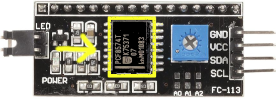
How to find the name of your port expander on the I2c
You need to provide the name of the I2c port expander that your board uses.
It should be written on the microchip that’s soldered on to your I2c board.
Supported port expanders are the PCF8574, the MCP23008 and the MCP23017.
The board on this photo has a PCF8574T port expander chip on it.
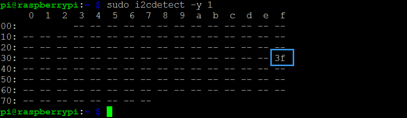
How to find your I2c addresss
You need to know the address of your I2c. You can find it on the command line using the “sudo i2cdetect -y 1” command.
In this case the address of the display is 0x3F.
How to change address on the I2c
You can change the address by making a bridge.
Soldering 1 or more wire on the back of the I2c (short circuit) A0, A1, A2
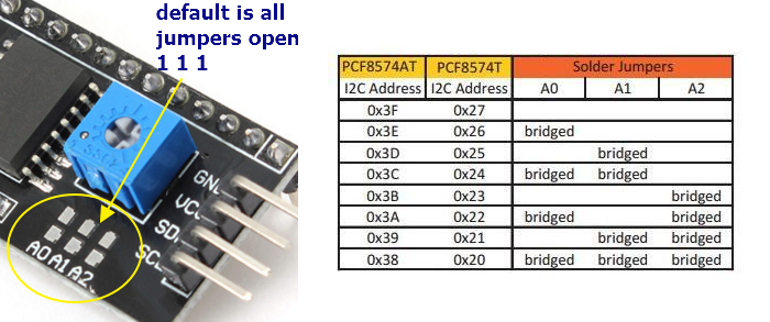
If your LCD has a PCF8574T chip from Texas Instruments, its default I2C address is 0x27Hex. If your LCD has a PCF8574AT chip from NXP semiconductors, its default I2C address is 0x3FHex. So your LCD probably has an I2C address 0x27Hex or 0x3FHex.
How to setup the LCD
Options are available by editing the configuration file
using the command - (All options can also be changed in the pibooth menu under “Lcd display setup”)
$ pibooth --config
How to setup “LCD DISPLAY SETUP” in either config.cfg or Pibooth menu
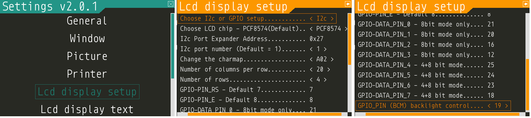
[LCD DISPLAY SETUP]
# Choose I2c(Default) or GPIO-4bit or GPIO-8bit setup
lcd_gpio_or_i2c = I2c
# Choose LCD chip - PCF8574(Default) or MCP23008 or MCP23017
lcd_chip = PCF8574
# Change Port Address 0x27(Default)
lcd_port_address = 0x27
# Change the I2C port number 1 or 2 - (Default = 1)
lcd_port = 1
# Change the I2C charmap A00 or A02 or ST0B - (Default = A02)
lcd_charmap = A02
# Number of columns per row 16 or 20 (16 = Default on a 16x2 LCD)
lcd_cols = 20
# Number of display rows 1 or 2 or 4 - (2 = Default on a 16x2 LCD)
lcd_rows = 4
GPIO ONLY - pin setup
# GPIO-PIN_RS - Default 7
lcd_pin_rs = 7
# GPIO-PIN_E - Default 8
lcd_pin_e = 8
# GPIO-DATA_PIN_0 - Default 21 (8 bit mode only)
lcd_data_pin4 = 21
# GPIO-DATA_PIN_1 - Default 20 (8 bit mode only)
lcd_data_pin5 = 20
# GPIO-DATA_PIN_2 - Default 16 (8 bit mode only)
lcd_data_pin6 = 16
# GPIO-DATA_PIN_3 - Default 12 (8 bit mode only)
lcd_data_pin7 = 12
# GPIO-DATA_PIN_4 - Default 25 (4+8 bit mode)
lcd_data_pin4 = 25
# GPIO-DATA_PIN_5 - Default 24 (4+8 bit mode)
lcd_data_pin5 = 24
# GPIO-DATA_PIN_6 - Default 23 (4+8 bit mode)
lcd_data_pin6 = 23
# GPIO-DATA_PIN_7 - Default 18 (4+8 bit mode)
lcd_data_pin7 = 18
# GPIO-Backlight_PIN - Default None (4+8 bit mode)
lcd_backlight_pin = None
How to setup “LCD DISPLAY TEXT” in either config.cfg or Pibooth menu
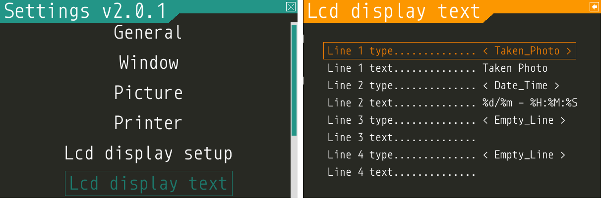
[LCD DISPLAY TEXT]
Select what to display on line 1,2,3,4
# This can also be changed in the pibooth menu under “LCD DISPLAY TEXT”
# Taken_Photo Printed Forgotten Remaining_Duplicates Date_Time Empty_Line Text
# Choose what to display on line 1,2,3,4
lcd_line_1_type lcd_line_2_type lcd_line_3_type lcd_line_4_type = etc. Taken_Photo
Write the text showing before the counter
# Text before etc. Taken Photo Counter is displayed - This can also be changed in the pibooth menu under “LCD DISPLAY TEXT”
Max-12 characters on a 16x2 display - Max 16 characters on a 20x4 display
lcd_line_1_text lcd_line_2_text lcd_line_3_text lcd_line_4_text = etc. Taken Photo, Printed, Forgotten, Duplicates
How to change the Date-Time format
See the Date-Time format codes in the following page
# You can change the way Date-Time is displayed - This can also be changed in the pibooth menu under “LCD DISPLAY TEXT”
Max-16 character on a 16x2 display - Max 20 character on a 20x4 display
# Default = %d/%m - %H:%M:%S
Choose Date_Time and use etc. %d/%m - %H:%M:%S to display the date and time
Write your own text on the display
# This can also be changed in the pibooth menu under “LCD DISPLAY TEXT”
# Text - Max-16 characters on a 16x2 display - Max 20 characters on a 20x4 display
Choose Text = Write your own text
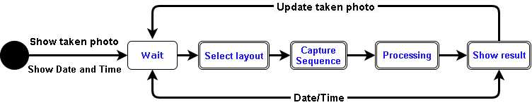
States description
Circuit diagram - only when using I2c - port expander
Here is the diagram for hardware connections.
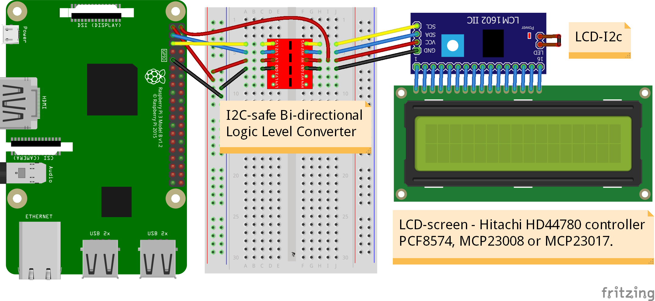
Wiring - only when using I2c - port expander
I2C-safe Bi-directional Logic Level Converter
When using a port expander with I2c on your LCD, you will have to use 5v.
Since the Raspberry Pi GPIO only handle 3.3v, it will therefore be a good idea to use a I2C-safe Bi-directional Logic Level Converter so you don’t fryed your pi.
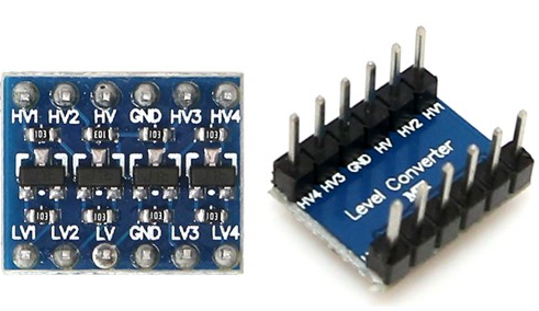
How to connect a Level Converter to your Port Expander and the Raspberry Pi
Connect the I2c Port Expander to HV (High Level) on the Level Converter.
GND: Pin GND (GND)
VCC: Pin HV (HV)(5v) - Also connect 5v from the raspberry Pi Pin 2, to HV on the Level Converter
SDA: Pin HV2 (HV2)
SCL: Pin HV1 (HV1)
Connect the Raspberry Pi (BOARD numbering scheme) to LV (Low Level) on the Level Converter.
GND: Pin 6 (GND)
3.3v: Pin 1 (LV)
SDA: Pin 3 (LV2)
SCL: Pin 5 (LV1)
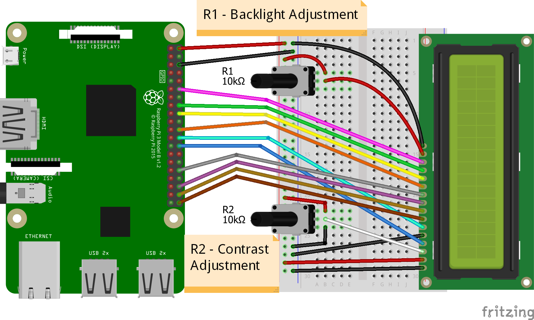
Circuit diagram - only when using GPIO - 4bit mode
Here is the diagram for hardware connections 4bit mode.
Circuit diagram - only when using GPIO - 8bit mode
Here is the diagram for hardware connections 8bit mode.
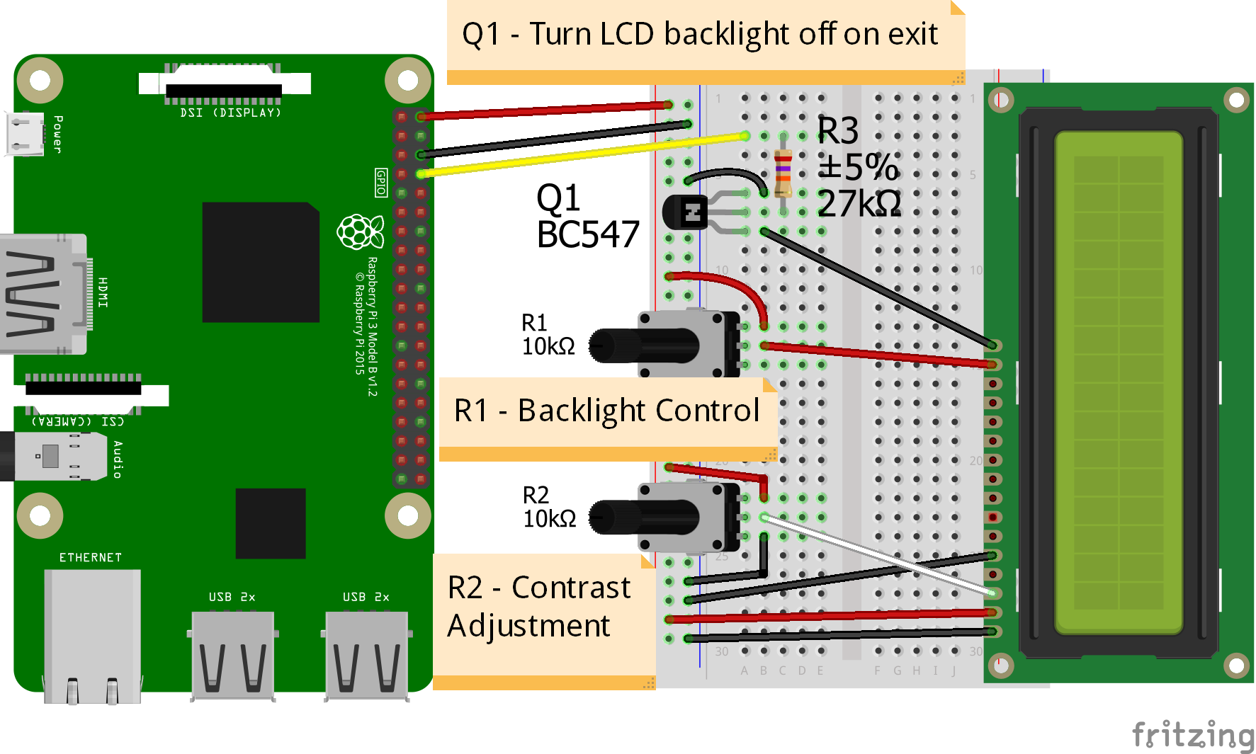
Circuit diagram - only when using GPIO - Turn off Backlight on exit - 4bit and 8bit mode
Here is the diagram for hardware connections If you want to automatic turn off Backlight, when Pibooth shutsdown optional.
Use an (Q1) NPN transitor BC547, BC548 or equivalent, which is activated by an additional GPIO connection. The LCD backlight is treated in exactly the same way as a switch for standard LED.
The base (middle wire) of the transistor is wired to an additional GPIO PIN via (R3) 27Kohm resistor. It then open and close LCD PIN 16 (GROUND) to control the backlight LED in the LCD.
Wiring - only when using GPIO 4bit or 8bit mode
First, connect the LCD Pins directly to the GPIO header of the Raspberry Pi: (BCM numbering scheme)
You can choose between 4bit mode (4 DATA wires “D4,D5,D6,D7”) or 8bit mode (8 DATA wires “D0,D1,D2,D3,D4,D5,D6,D7”) 8bit mode is faster and often more stable than 4bit mode.
If you don’t know how to wire up the LCD to the Raspberry Pi, use some of the above examples.
Connect PINS from the LCD, to the raspberry Pi.
LCD |
GPIO (BCM scheme) |
BOARD numbering scheme |
|---|---|---|
|
(Ground) |
PIN 6 |
|
5v Power |
PIN 2 |
|
Middle wire of the |
R2 potentiometer. |
|
GPIO7 |
PIN 26 |
|
(Ground) |
PIN 6 |
|
GPIO8 |
PIN 24 |
|
GPIO21 |
PIN 40 |
|
GPIO20 |
PIN 38 |
|
GPIO16 |
PIN 36 |
|
GPIO12 |
PIN 32 |
|
GPIO25 |
PIN 22 |
|
GPIO24 |
PIN 18 |
|
GPIO23 |
PIN 16 |
|
GPIO18 |
PIN 12 |
|
Middle wire of the |
R1 potentiometer. |
|
(Ground) |
PIN 6 |
NOTE :
The RW pin allows the device to be be put into read or write mode.
We wanted to send data to the LCD device but did not want it to send data to the Pi so we tied this pin to ground.
The Pi can not tolerate 5V inputs on its GPIO header.
Tying RW to ground makes sure the LCD device does not attempt to pull the data lines to 5V which would damage the Pi.
((NOT ALL OLD LCDs CAN USE 5v, CHECK YOUR LCD SPEC. Or test it with 3v3 first))
R1: Potentiometers: 10K Ohms. But can be substituted with and resistors.
R2: Potentiometers: 10K Ohms. Controls the contrast and brightness of the LCD. Using a simple voltage divider with a potentiometer, we can make fine adjustments to the contrast.
Release history Release notifications | RSS feed

Download files
Download the file for your platform. If you're not sure which to choose, learn more about installing packages.
Source Distributions
Built Distribution
Filter files by name, interpreter, ABI, and platform.
If you're not sure about the file name format, learn more about wheel file names.
Copy a direct link to the current filters
File details
Details for the file pibooth_lcd_display-2.0.0-py2.py3-none-any.whl.
File metadata
- Download URL: pibooth_lcd_display-2.0.0-py2.py3-none-any.whl
- Upload date:
- Size: 21.8 kB
- Tags: Python 2, Python 3
- Uploaded using Trusted Publishing? No
- Uploaded via: twine/3.4.1 importlib_metadata/4.6.1 pkginfo/1.7.1 requests/2.21.0 requests-toolbelt/0.9.1 tqdm/4.61.2 CPython/3.7.3
File hashes
| Algorithm | Hash digest | |
|---|---|---|
| SHA256 |
9884fecb81e532e46a57afae2b752fd2bd7898576ddec7148598c374fd3bd77b
|
|
| MD5 |
0c5a79585c1f0b6ceef5bcbcc04a6d97
|
|
| BLAKE2b-256 |
f09c6bbb5017b98f7df2e44008899894697b914b17b173c109ff30b1f9c44fd9
|


