Pibooth Plugin to manage small OLED displays (via I2c or SPI). Show various counters (e.g., photos taken), display time-date, text, logos, and animated GIFs.

Project description


pibooth-oled-display is a plugin for the pibooth application.
(parallel mode will not be suported).
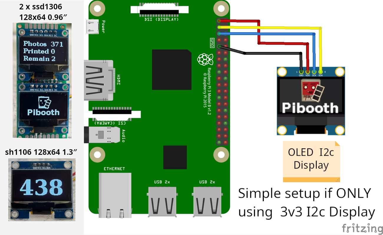
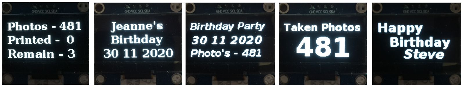
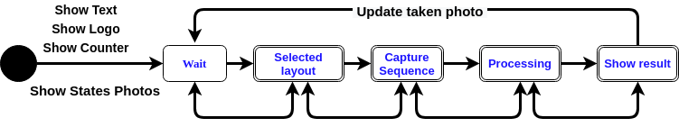
It can show up to 3 lines of Text, with or without Counters, with numbers of Photos Taken, Printed Photos, Forgotten Photos, Remaining Duplicates. Or Date-Time, Text_Only or an Empty line.


Don’t be scared by this long manual, it´s there to cover all the different OLED displays on the marked. If you only have an 3v3 I2c OLED display all you need is 4 wires to your Pi, and installing the plugin.
Requirements
Hardware
1 x Raspberry Pi 3 Model B (or higher).
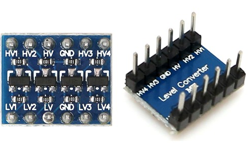
1 x I2c safe Logic Level Converter (If you are using 5v displays).
1 x OLED-display, with I2c or SPI (See the list of Tested OLED Displays).
Tested OLED Displays
Here is the list of supported displays by the luma.oled driver
OLED displays |
Display Resolutions |
TESTED |
SPI |
I2C |
|---|---|---|---|---|
|
128x64 |
Working |
X |
X |
|
128x32, 128x64 |
Working |
X |
X |
|
not tested |
|||
|
not tested |
|||
|
not tested |
|||
|
not tested |
|||
|
not tested |
|||
|
not tested |
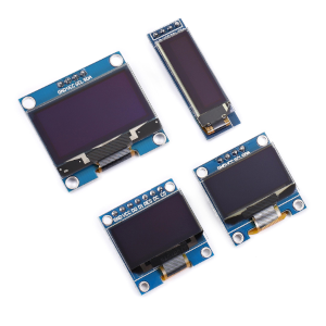
Most common OLED displays are these 3 (I prefer size 0.96, 1.3 or higher″)
ssd1306 128x32 0.91″ 128X32 white Display
ssd1306 128x64 0.96″ 128X64 white Display
sh1106 128x64 1.3″ 128X64 white Display
Install
$ pip3 install pibooth-oled-display
I2c Configuration
Enabling I2c interface on the Raspberry Pi
There are two methods to enable I2c.
I recommend checking the official Raspberry Pi documentation or the latest resources provided by the Raspberry Pi community. They will provide the most accurate instructions for configuring the I2C interface on your specific version of the Raspberry Pi.
Raspberry Pi Configuration via Desktop GUI
You can use the Desktop GUI by heading to the Pi Start Menu > Preferences > Raspberry Pi Configuration.
A window will pop up with different tabs to adjust settings. What we are interested is the Interfaces tab.
Click on the tab and select Enable for I2C. Click on the OK button to save.
We recommend restarting your Pi to ensure that the changes to take effect.
Click on the Pi Start Menu > Preferences > Shutdown. Since we just need to restart, click on the Restart button.
raspi-config Tool via Terminal
Again, we can use raspi-config to enable it.
Run sudo raspi-config
Use the down arrow to select 5 Interfacing Options
Arrow down to P5 I2C
Select yes when it asks you to enable I2C
Also select yes if it asks about automatically loading the kernel module.
Use the right arrow to select the <Finish> button.
Select yes when it asks to reboot.
The system will reboot. when it comes back up, log in and enter the following command in terminal
ls /dev/*i2c*
The Pi should respond with
/dev/i2c-1
Which represents the user-mode I2C interface.
How to find your I2c addresss
You can find it writing this command in the command line:
sudo i2cdetect -y 1
In this case the address of the display is 0x3C.

How to change I2c address
On most displays you can solder a (short circuit) on the back of the OLED display, to change the address.
(check the manual of your display, or search the internet)
SPI Configuration
Enabling SPI interface on the Raspberry Pi
There are two methods to adjust the settings.
I recommend checking the official Raspberry Pi documentation or the latest resources provided by the Raspberry Pi community. They will provide the most accurate instructions for configuring the SPI interface on your specific version of the Raspberry Pi.
Raspberry Pi Configuration via Desktop GUI
You can use the Desktop GUI by heading to the Pi Start Menu > Preferences > Raspberry Pi Configuration.
A window will pop up with different tabs to adjust settings. What we are interested is the Interfaces tab.
Click on the tab and select Enable for SPI. Click on the OK button to save.
We recommend restarting your Pi to ensure that the changes to take effect.
Click on the Pi Start Menu > Preferences > Shutdown. Since we just need to restart, click on the Restart button.
raspi-config Tool via Terminal
Again, we can use raspi-config to enable it.
Run sudo raspi-config
Use the down arrow to select 3 Interfacing Options
Arrow down to P4 SPI
Select yes when it asks you to enable SPI
Also select yes if it asks about automatically loading the kernel module.
Use the right arrow to select the <Finish> button.
Select yes when it asks to reboot.
The system will reboot. when it comes back up, log in and enter the following command in terminal.
ls /dev/spidev*
/dev/spidev0.0 /dev/spidev0.1 If SPI is not enabled, you will see an error message or no output.
I2c Circuit diagram and wiring - (ONLY with 3v3 displays)
I2c Circuit diagram - (ONLY with 3v3 displays)
IMPORTANT use ONLY 3v3
The Vcc and GND on the OLED displays are not always the same, so it is verry important that you check Vcc and GND is set correctly.
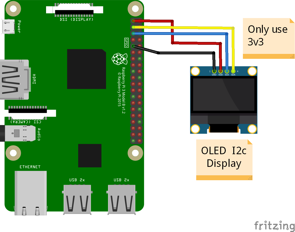
I2c Wire - (ONLY with 3v3 displays)
3v3 only. IMPORTANT CHECK YOUR DISPLAY FOR THE RIGHT CONNECTION
Display Pins |
RPi-PINs |
Info |
|---|---|---|
VCC 3v3 |
PIN 1 |
3v3 ONLY |
GND (Ground) |
PIN 6 |
Ground pin of the module |
SCL (Clock) |
PIN 5 |
Acts as the clock pin. |
SDA (Data) |
PIN 3 |
Data pin of the module. |
I2c Circuit diagram - (5v displays) with an Logic Level Converter
I2C circuit diagram - (5v displays)
Here is the diagram for hardware connections with and Logic Level Converter. IMPORTANT The Vcc and GND on the OLED display are not always the same, so it is verry important that you check Vcc and GND is set correctly.
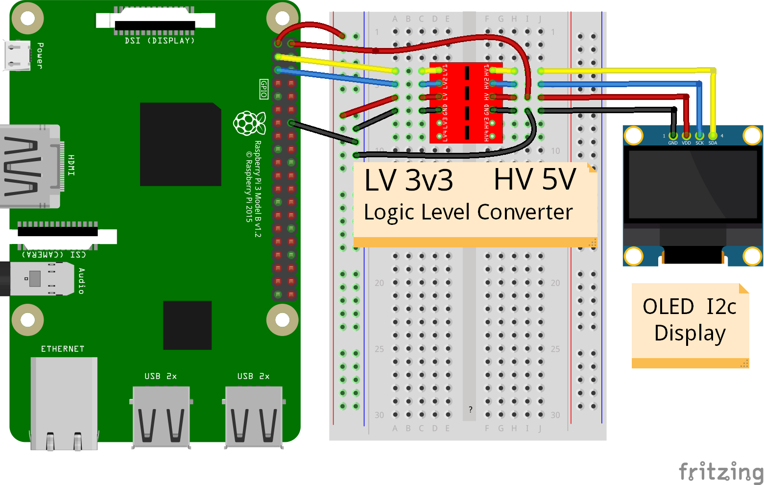
I2c wire - (5v displays)
IMPORTENT: If you use 5v to power the OLED display most OLEDs can also run on 3v3, check your manual.
Since the Raspberry Pi GPIO only handle 3.3v, it will therefore be a good idea to use a Logic Level Converter when using 5v to power the display, so you don’t fryed your pi.
IMPORTANT CHECK YOUR DISPLAY FOR THE RIGHT CONNECTION
(Display >> level converter HV side)
Display Pins |
Level converter |
Info |
|---|---|---|
GND |
GND |
Dsplay GND to the level converter GND |
VCC |
HV (HV ) |
Display VC to the level converter HV |
SCL (Clock) |
HV2 (HV2) |
SCL <> HV2 on the Level Converter |
SDA (Data) |
HV1 (HV1) |
SDA <> HV1 on the Level Converter |
(Raspberry Pi >> Level converter LV side)
RPi |
Pins |
Level converter |
Info |
|---|---|---|---|
GND |
Pin 6 |
GND |
RPi GND to GND on the level converter |
3.3v |
Pin 1 |
LV (LV ) |
RPi (3v3) to LV on the Level Converter |
5v |
Pin 2 |
HV (HV ) |
RPi (5v) to HV on the Level Converter |
SCL |
Pin 5 |
LV2 (LV2) |
SCL <> LV2 on the Level Converter |
SDA |
Pin 3 |
LV1 (LV1) |
SDA <> LV1 on the Level Converter |
SPI Circuit diagram and Wiring
SPI circuit diagram (ONLY with 3v3 displays)
Here is the diagram for hardware connections without and Logic Level Converter.
If your OLED display use 5v instead of 3v3, it demands an 8 Channel Logic Level Converter, you should get one or you risk frye your pi.
IMPORTANT The Vcc and GND on an OLED display are not always the same, so it is verry important that you check Vcc and GND is set correctly.
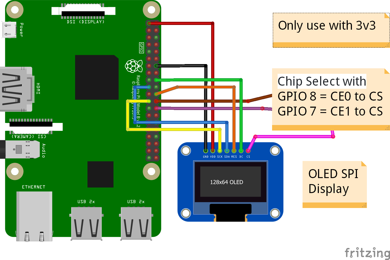
SPI wire setup - (ONLY with 3v3 displays)
7 Pins |
Remarks |
RPi-PIN |
RPi GPIO |
Info |
|---|---|---|---|---|
VCC |
Power Pin |
PIN 1 |
3V3 |
3V3 ONLY - CHECK YOUR DISPLAY |
GND |
Ground |
PIN 6 |
GND |
Ground pin of the module |
D0, SCL |
Clock |
PIN 23 |
GPIO 11 (SCLK) |
Acts as the clock pin. |
D1, SDA |
MOSI |
PIN 19 |
GPIO 10 (MOSI) |
Data pin of the module. |
RST |
Reset |
PIN 22 |
GPIO 25 |
Resets the module, useful during SPI |
DC, A0 |
Data/Command |
PIN 18 |
GPIO 24 |
Data Command pin. Used for SPI protocol |
CS |
Chip Select |
PIN 24 PIN 26 |
GPIO 8 (CE0) GPIO 7 (CE1) |
Useful when more than one module is used under SPI protocol Useful when more than one module is used under SPI protocol |
If you have a 8 pins OLED display with “Vin” connect 3v3 to Vin and leave VCC empty. (or check the internet for more info on how to setup your display)
SPI wire - (5v display) with a Logic Level Converter
You will need a 8 channel Logic Level Converter to use SPI with 5v. Or you can use 2 x 4 channels Logic Level Converters.
You take the needed GPIO PINs from the Raspberry Pi, and wire them to the LV side of the Logic Level Converters.
The same goes for 3v3 wire, that goes to the LV side of the level converters.
You also need to wire the 5v from the Raspberry Pi to the HV side of the level converter.
And last you need GND (Ground) from the Raspberry Pi to GND one or both sides of the level converters.
States
States images
Look at How to show your own States images.
´processing´ ´print´ ´finish´ ´failsafe´
States description
Setup in Pibooth Menu
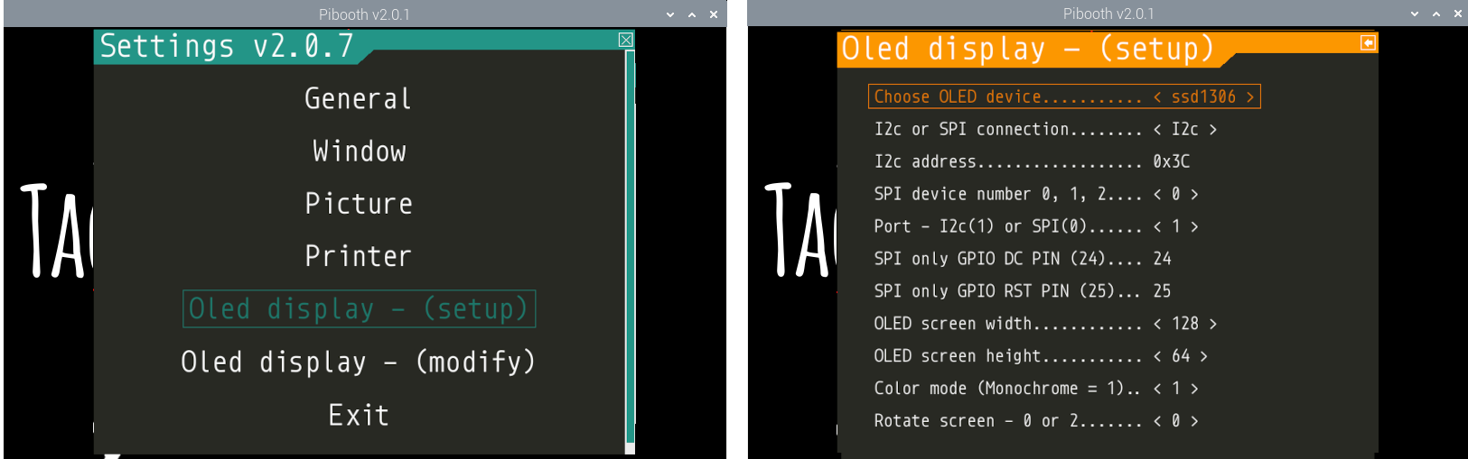
OLED Display - (SETUP) - Pibooth Menu
Be aware that this plugin can sometimes make the reaction to enter the menu slow (2-3 sec).
which permits to configure the behavior of the plugin.
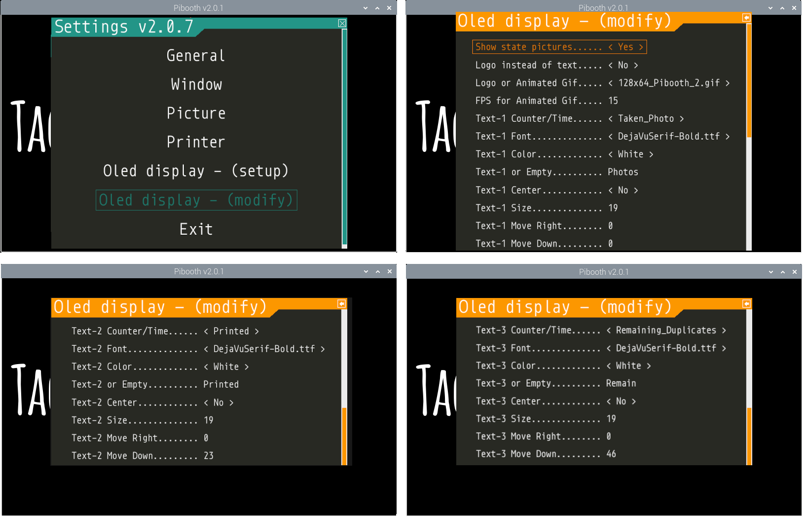
OLED Display - (MODIFY) - Pibooth Menu
Be aware that this plugin can sometimes make the reaction to enter the menu slow (2-3 sec).
which permits to configure the behavior of the plugin.
Setup in config.cfg
under Oled display - (setup) and Oled display - (modify)
Edit config.cfg by using the command line or a text editor
$ pibooth --config
OLED DISPLAY - (SETUP) - config.cfg
config.cfg
oled_devices = ssd1306
oled_i2c_or_spi = I2c
oled_port_address = 0x3c
oled_spi_device_number = 0
oled_port = 1
oled_spi_gpio_dc_pin = 24
oled_spi_gpio_rst_pin = 25
oled_width = 128
oled_height = 64
oled_color_mode = 1
oled_rotate = 0
OLED DISPLAY - (MODIFY) - config.cfg
oled_states_pictures = Yes
oled_showlogo = No
oled_logos = 128x64_Pibooth_2.gif
oled_animated_fps = 15
oled_counter_type1 = Taken_Photo
oled_font_1 = DejaVuSerif-Bold.ttf
oled_text1_color = white
oled_text_1 = "Photos "
oled_text_1_center = No
oled_size_1 = 19
oled_text1_right = 0
oled_text1_down = 0
oled_counter_type2 = Printed
oled_font_2 = DejaVuSerif-Bold.ttf
oled_text2_color = white
oled_text_2 = "Printed "
oled_text_2_center = No
oled_size_2 = 19
oled_text2_right = 0
oled_text2_down = 23
oled_counter_type3 = Remaining_Duplicates
oled_font_3 = DejaVuSerif-Bold.ttf
oled_text3_color = white
oled_text_3 = "Remain "
oled_text_3_center = No
oled_size_3 = 19
oled_text3_right = 0
oled_text3_down = 46
How to use Date-Time / Logo / Animated Gif
How to change the Date-Time format
You can also find the file Date-Time_Format_Codes.rst in your local pibooth config folder ~/.config/pibooth/oled_display/ after you run the plugin the first time.
Choose Date_Time in the menu - (If you leave the text field empty, the Default will be used = %H:%M:%S).
Or use semething like this %d/%m - %H:%M:%S in the text field to display the date and time.
Remember to set the size of the text to match the display, after you set your Date-Time format codes.
How to show your own Logo
Also look at How to show your own Animated Gif as logo.
Logo path = ~/.config/pibooth/oled_display/logo/
If you add an images with the same name and File extension(s) as some of the default images, only the user images will be showing.
When adding new Logo, you need to restart Pibooth to load it into the logo database. If you delete a user logo that is still in the configuration a default Pibooth Logo will be showing on the display
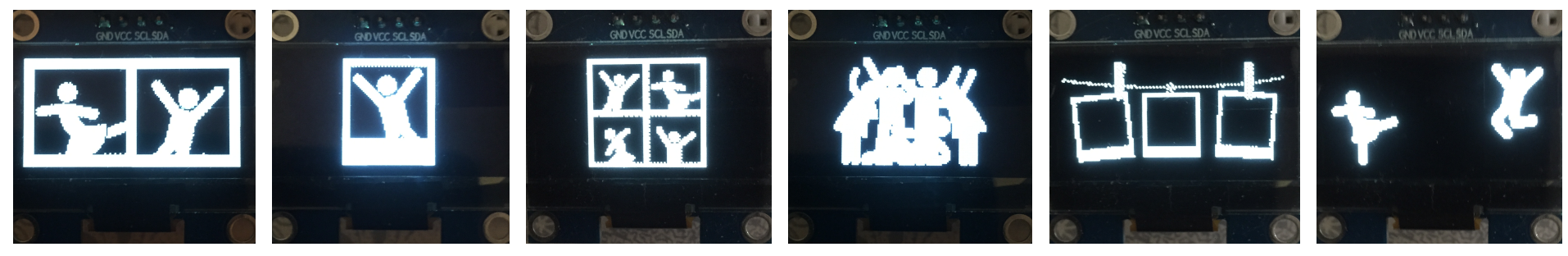
How to show your own Animated Gif
An choose Yes in Logo instead of text in the Pibooth Menu
On Monochrome displays (black & white) you need the Animated Gif to have a Black bagground. The reason for that is that the luma.oled drivers converts transperent to white color, when using color mode 1.
All images will be centered automatic on the display.
But they are not always showing correct, as they will be converted to Black and White or grayscale.
When adding new Animated Gif, you need to restart Pibooth to load them into the Logo database. If you delete a user Animated that is still in the configuration a default Pibooth Logo will be showing on the display
How to show your own States images
256 x 128 pixels 256 x 256 pixels 320 x 240 pixels
States path = ~/.config/pibooth/oled_display/states/
When adding a new states images, it will automatic be used instead of default.
There are 8 folders, and you need 11 .png images with the static names “folder and resolution”. Here is an examble on how you should name your states images if you have an display with resolution 128 x 64. You should make images with the same resolution as you display and use the static names with resolution as below, and put them in every folder under each states.
Examples : 128x32 = processing_128x32.png 128x64 = processing_128x64.png
states/processing/ processing_128x64.png
states/processing/origin/ processing_128x64.xcf
you need to make a new images and put it in each states folder or display will be empty if states is activated.
If you have an monochrome display with the resolution 128x64, you can convert or make an image to that resolution (in 8-bit mode).
When adding new States images, you need to restart Pibooth to load them into the States database. If you delete a user State image the default Pibooth States images will be showing on the display
How to add your own Fonts
~/.config/pibooth/oled_display/fonts/
Supported font types are ´´.ttf´´ or ´´otf´´
only the user Fonts will be showing in the menu.
You can download free fonts online, on sites like fontspace.com
When adding new fonts, you need to restart Pibooth to load them into the fonts database. If you delete a user Font that is still in the configuration the default Font ‘DejaVuSerif-Bold.ttf’ will be used on the display
Tips & Tricks
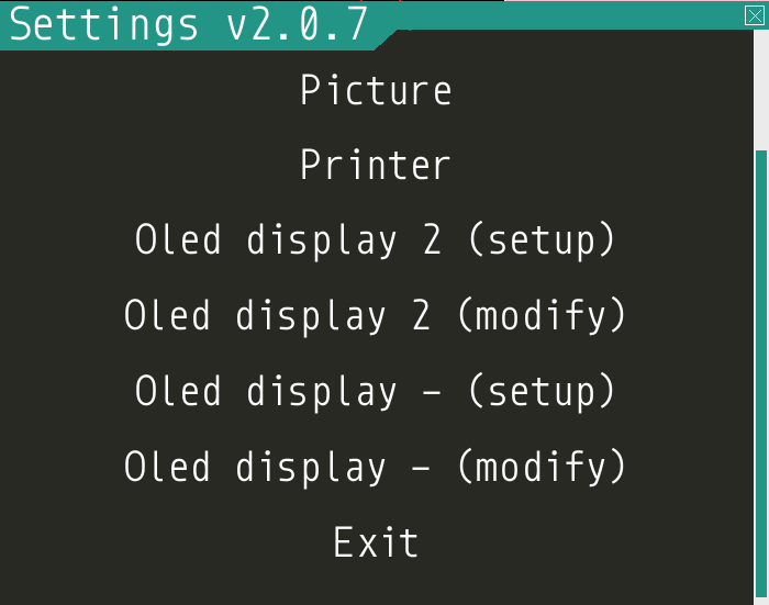
How to use 2 x OLED displays at the same time
How to install the second display plugin “pibooth_oled_display_2.py”
The extra plugin for display 2 “pibooth_oled_display_2.py” is automatic in the folder ~/.config/pibooth/oled_display/ after you run the plugin the first time.
You can activate the plugin by adding path to the file, to custom plugins in the config.cfg file under [GENERAL].
Open the config.cfg with this command, and find the line “plugins =”
$ pibooth --config
plugins = '~/.config/pibooth/oled_display/pibooth_oled_display_2.py'
Oled display 2 - (Setup) and Oled display 2 - (modify)
Go to the menu and setup your new second display. If you are using I2c, you new display 2 need its own I2c addresses (standard 0x3d).
If you use SPI, you need to have 2 displays with the CS (Chip Select) option (this funktion has not yet been tested, but should work).
Setup 2 x I2c OLED displays - (Showing seperate things on each display)
You will need 2 x I2c OLED displays with different I2c addresses. defaults are 0x3c on display 1, and 0x3d on display 2.
On most displays you can change the I2c address on the back of your OLED display with some soldering.
Or you can get an 8 Channel I2C Muti-Channel Expansion Development Board to convert the default address to an new address and then use up 8 x I2c displays at the same time.
Setup 2 x SPI OLED displays - (Showing seperate things on each display)
And if it work, it will only work if you have the CS PIN on the displays.
Both the displays uses the same PINs/GPIOs, except the CS (Chip Select) PIN
On display 1. Put a wire from the CS PIN to GPIO 8 (pin24) to choose CE0.
On display 2. Put a wire from the CS PIN to GPIO 7 (pin26) to choose CS1.
Check online for more info about your displays on how to set them up.
According to LUMA.oled driver documentation, you should choose port 0 for display 1 and port 1 for display 2.
You can do that in the pibooth menu. An maybe also try change the SPI device number to 0,1 or 2 to make it work.
Can i use SPI1 ? (e.g.SPI and SPI1 together on the pi)
I dont think it is suported by the luma.oled drivers.
So only SPI (SPI0) can be used.
Setup 2 x OLED displays - (Showing the same things on each display)
On the I2c displays, you just use the same port address (0x3c etc.), and wire them to the same GPIO PINs.
On the SPI displays, you just use the same CS port address (CE0 etc.), and wire them to the same GPIO PINs.
How to use a OLED displays with only 6 pins I2c/SPI
but unfortunately you can only use one display in pibooth, as there is no CS pin on the display.
It also works when using 2 displays in pibooth.
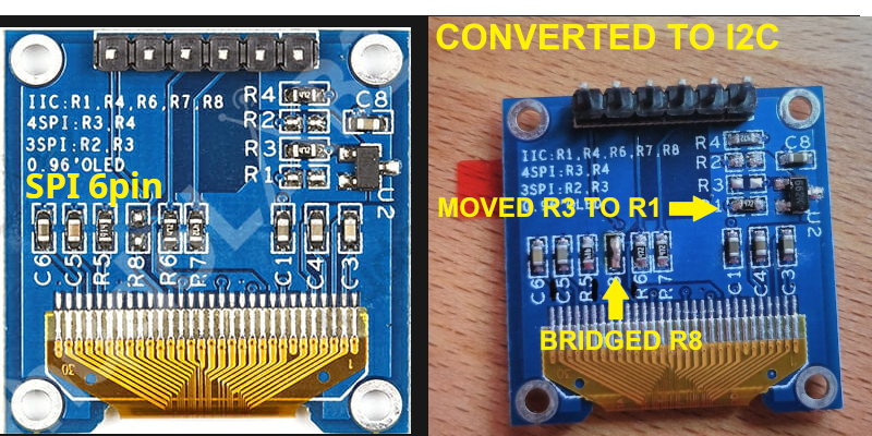
DC >> VCC = for I2C address 0x3c
DC >> GND = for I2C address 0x3d
So you need a 10k resistor, and a 47nf or 100nf capacitor (Ceramic or Electrolytic)
Reset pin >> 10k resistor >> VCC
Reset pin >> 47nF or 100nF capacitor (condensator) >> GND (Ground)
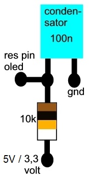
The purpose of this circuit is to provide a stable voltage level and proper reset functionality for the Reset pin of the OLED display. The 10k resistor connected between the Reset pin and VCC is the pull-up resistor, which ensures that the Reset pin remains at a high logic level when it is not actively driven low.
The 47nF or 100nF capacitor connected between the Reset pin and ground serves to stabilize the reset signal by filtering out any noise or voltage fluctuations. It helps ensure that the reset signal is clean and reliable, preventing false triggering or erratic behavior.
By using this pull-up and reset circuit, you are ensuring that the OLED display receives a proper reset signal and is able to turn on reliably. It is a common practice to include these components to ensure the correct functioning of cheap displays with reset pins.
Release history Release notifications | RSS feed


Download files
Download the file for your platform. If you're not sure which to choose, learn more about installing packages.
Source Distributions
Built Distribution
Filter files by name, interpreter, ABI, and platform.
If you're not sure about the file name format, learn more about wheel file names.
Copy a direct link to the current filters
File details
Details for the file pibooth_oled_display-2.0.3-py2.py3-none-any.whl.
File metadata
- Download URL: pibooth_oled_display-2.0.3-py2.py3-none-any.whl
- Upload date:
- Size: 7.5 MB
- Tags: Python 2, Python 3
- Uploaded using Trusted Publishing? No
- Uploaded via: twine/4.0.2 CPython/3.9.2
File hashes
| Algorithm | Hash digest | |
|---|---|---|
| SHA256 |
cb7b370e322700faa4257fb8464a997aad3e9ec31ecc432c7ed735897f65b080
|
|
| MD5 |
0fdf95c14c7124237adac48c3a892f08
|
|
| BLAKE2b-256 |
96e09130cb5a7718879820c67d35f3b06189fb8d4ecfa0574da25f017cb0d162
|


