USB-C 12-Channel Servo Controller


12-channel USB-C servo controller, Pololu Maestro compatible, with an MCP server so AI agents (Claude, etc.) can drive servos. $18 on Tindie · product page.
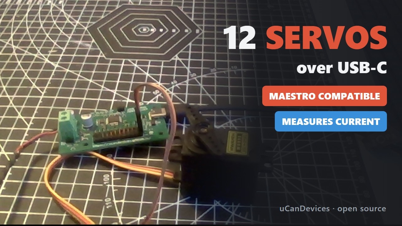
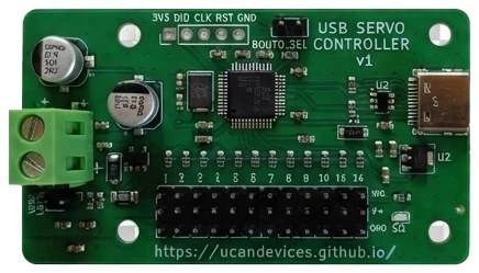
▶ 2-minute video: wiring, current monitoring, GUI and the controller driving a real MG995
Open-source alternative to the Pololu Mini Maestro 12 that speaks the Maestro serial protocols, so Maestro libraries work unchanged — plus USB-C, servo-rail current and voltage sensing, on-board scripts. Built for JLCPCB turnkey assembly, ≈ $4.43 per board at 100 units against $29.95 for the Maestro.
| MCU | WCH CH32V203C8T6, RISC-V 96 MHz, LQFP-48 |
| Channels | 12 hardware PWM, 50 Hz, 0.5 µs; travel limits per channel (64–4080 µs, 500–2500 default); analog input on 0–7 |
| Host interface | USB-C, CDC serial (no driver); ASCII protocol and the Pololu Maestro Compact / Pololu / Mini SSC protocols |
| Servo power | separate rail on a 5.08 mm screw terminal, 5–13.2 V full function, ~5 A total |
| Sensing | rail current (5 mΩ + INA180A2) and voltage (÷4), overcurrent / LiPo undervoltage cut-off |
| PCB | 66 × 38 mm, 2 layers, all parts top side, 4 × M3 |
| Status | first board verified on hardware 2026-09-28 — selftest.py --rail --move 58/58; channels 1–11 not yet driven with a real servo |
| Document | For |
|---|---|
USER.md |
using the board: wiring, power, tools, command reference, flashing |
tools/README.md |
host tools: library, CLI, GUI, scripts, MCP server, release builds |
| this file | design: why each choice, BOM and cost, limitations, what is left before fab |
AI agents (MCP server)
tools/servo_mcp.py is an MCP server that lets an AI agent move servos,
run poses and sequences, and read rail current/voltage, with guardrails: per-channel limits,
ramped moves, overcurrent stop. pip install -r tools/requirements.txt, then:
Claude Code
claude mcp add servo -- python /path/to/UsbServoController/tools/servo_mcp.py
Claude Desktop (claude_desktop_config.json)
{
  "mcpServers": {
    "servo": {
      "command": "python",
      "args": ["/path/to/UsbServoController/tools/servo_mcp.py"]
    }
  }
}
Add "--port", "COM5" to pick a port, or "--mock" to try it without hardware.
Close the GUI first: only one program can hold the serial port.
The server is also on PyPI, so any MCP client can run it without cloning the repo:
command uvx, args ["ucan-servo-mcp"] (plus --config path/to/servogui.json
to use the limits, poses and sequences saved by the GUI).
1. Quick start
pip install -r tools/requirements.txt
python tools/servogui.py              # GUI (or --mock with no hardware)
python tools/servoctl.py set 0 1500   # CLI
cd embedded-ch32 && make flash        # build + flash over USB, ~3 s, no jumper
Downloads: firmware images and the prebuilt GUI for Windows and Linux are on the
Releases page.
To build the GUI yourself: python tools/build_release.py → tools/dist/.
2. Why the CH32V203C8T6
The hard requirement was a USB bootloader in ROM, so a blank chip can be flashed over USB-C with no programmer. That rules out the STM32F103 the design started on (USART-only bootloader). Of LQFP-48 parts that have one and are stocked at JLCPCB:
| Candidate | USB boot on blank chip | Stock | $@100 |
|---|---|---|---|
| CH32V203C8T6 (chosen) | ✅ | 8,643 | 0.877 |
| CH32X035C8T6 / CH32F203C8T6 | ✅ | ~500 | 0.72 / 1.02 |
| AT32F415CBT7 | ✅ | 10,518 | 1.319 |
| STM32F072C8T6 | ✅ | 2,945 | 2.495 |
Cheapest part with real inventory, a third the price of the STM32F072, and pin-compatible with the STM32F103 layout (32 of 33 connected pins identical).
Costs of the choice:
- RISC-V firmware, WCH HAL, no CubeMX.
- An ST-Link will not work. Debug is WCH 2-wire SDI on J9 — needs a WCH-LinkE. Routine flashing is over USB, so the probe is only for debugging.
- PB2 is BOOT1 on this chip, so it is tied low by R17 (5.1 kΩ).
3. Hardware
                            U4 INA180A2 (Kelvin across R18) ─► PA5 I_SENSE
J2 Servo V+ ── R18 5mΩ ──┬────────► servo header V+ rail (unfused)
  (VSRV_RAW)              ├─ R19..R22 ÷4 ─► PA4 V_SENSE
                          └─ JP1 ──D2──┐
                                       ├─► HT7533-1 ─► 3V3 ─► CH32V203, LED
USB-C VBUS 5V ─────────────D1──────────┘
GND: one continuous plane, common to both supplies
- Two supply domains, one ground. D1/D2 are a diode-OR so neither feeds the other. Every servo amp crosses R18, so the current reading covers the whole board.
- JP1 (2-pin header, open by default): fit a shunt cap to run the logic from
the servo supply with no USB — the Maestro's
VSRV=VINblock. - JP2 (2-pin header): BOOT0 high, for first flash / recovery only.
- Logic draw ≈ 15 mA, so the HT7533-1 (100 mA, 2.5 µA quiescent) dissipates 0.07 W even from 2S LiPo.
- USB-C: CC pull-downs R14/R15, SRV05-4 clamps D+, D−, CC1, CC2.
- Servo signals are 3.3 V through 220 Ω (R1–R12). Headers are SIG / V+ / GND.
Channel map
| Ch | 0 | 1 | 2 | 3 | 4 | 5 | 6 | 7 | 8 | 9 | 10 | 11 |
|---|---|---|---|---|---|---|---|---|---|---|---|---|
| Pin | PA0 | PA1 | PA2 | PA3 | PA6 | PA7 | PB0 | PB1 | PA8 | PA9 | PA10 | PB8 |
| Timer | T2C1 | T2C2 | T2C3 | T2C4 | T3C1 | T3C2 | T3C3 | T3C4 | T1C1 | T1C2 | T1C3 | T4C3 |
| Analog | ✅ | ✅ | ✅ | ✅ | ✅ | ✅ | ✅ | ✅ | — | — | — | — |
Reserved: PA4/PA5 rail sensing · PA11/PA12 USB · PA13/PA14 SDI · PD0/PD1 crystal · PC13 LED · PB2 BOOT1. LQFP-48 has only 10 ADC pins, and PA4/PA5 went to sensing, so analog is 8 of 12 — the Maestro 12 has all twelve.
Rail sensing
| Current (R18 + U4) | Voltage (R19–R22) | |
|---|---|---|
| Parts | 5 mΩ 1 W shunt, INA180A2 gain 50, high side | 4 × 5.1 kΩ, ÷4, 100 nF |
| Full scale | 13.2 A | 13.2 V |
| Resolution | ≈ 3.2 mA | ≈ 3.2 mV |
High side keeps the ground plane unbroken. It measures total rail current, not per channel. The ADC reference is VDDA = the LDO output (no VREF+ on LQFP-48), so readings are good for thresholds, not calibrated metering. The firmware trips all channels off after 5 bad readings (~50 ms): 5 A default overcurrent, and undervoltage chosen automatically (2S → 6.4 V, 3S → 9.6 V, anything else off). Details in USER.md §4.4.
Power limits
| Limit | Set by | Value |
|---|---|---|
| Absolute max on J2 | C15/C16, 16 V electrolytics | 16 V |
| Full function (voltage sense) | ÷4 divider | 13.2 V |
| Continuous current | 2.4 mm pour between header rows | ~5 A (6.1 A at 20 °C rise) |
The 24 A terminal is not the limit; the copper behind it is.
PCB
2 × 1 oz, 1.6 mm, 0.2 mm min trace/space, 0.3/0.6 mm vias. GND is a solid pour on both layers; SERVO_V+ is carried by three priority-ordered top-layer zones. Headers along the bottom edge, USB-C right, screw terminal left, MCU centre.
⚠️ F8 (Update PCB from Schematic) deletes H1–H4 — they have no schematic symbol. Untick Delete footprints with no symbols, or re-add them at (16, 4), (61.5, 4), (16, 33), (61.5, 33).
⚠️ HT7533-1 is not pin-compatible with the AMS1117 it replaced (SOT-89: GND / VIN+tab / VOUT). The tab is VIN.
4. Bill of materials and cost
Class: B Basic · P Preferred (both fee-free) · E Extended ($3.07 feeder fee if SMT).
| Ref | Part | LCSC | Class | Qty | $/board |
|---|---|---|---|---|---|
| U1 | CH32V203C8T6, LQFP-48 | C3001172 | E | 1 | 0.8770 |
| U2 | HT7533-1, SOT-89-3 | C14289 | B | 1 | 0.1430 |
| U3 | SRV05-4 ESD, SOT-23-6 | C558418 | E | 1 | 0.0270 |
| U4 | INA180A2, SOT-23-5 | C192764 | E | 1 | 0.1920 |
| J1 | USB-C 16P TYPE-C-31-M-12 | C165948 | E | 1 | 0.1860 |
| J2 | Screw terminal 5.08 mm 2P | C474952 | E (THT) | 1 | 0.1920 |
| J3–J8 | Pin header 1×6 2.54 mm | C37208 | E (THT) | 6 | 0.2520 |
| JP1, JP2 | Pin header 1×2 2.54 mm | C358684 | E (THT) | 2 | 0.0180 |
| Y1 | Crystal 8 MHz SMD5032 | C115962 | B | 1 | 0.2450 |
| D1–D2 | B5819W, SOD-123 | C7420330 | P | 2 | 0.0340 |
| D3 | LED red 0603 | C2286 | B | 1 | 0.0070 |
| R1–R13 | 220 Ω 0603 (servo series + LED) | C22962 | B | 13 | 0.0650 |
| R14–R17, R19–R22 | 5.1 kΩ 0603 | C23186 | B | 8 | 0.0160 |
| R18 | 5 mΩ 1 W shunt, 1206 | C7419996 | E | 1 | 0.0370 |
| C1–C8, C17–C18 | 100 nF 0603 X7R | C14663 | B | 10 | 0.1200 |
| C9–C11 | 10 µF 0603 X5R | C19702 | B | 3 | 0.0960 |
| C12 | 1 µF 0603 | C15849 | B | 1 | 0.0170 |
| C13–C14 | 30 pF 0603 C0G | C1658 | B | 2 | 0.0160 |
| C15–C16 | 470 µF 16 V electrolytic | C46550400 | E | 2 | 0.2140 |
| 58 | $2.7540 |
J9 (SDI) is not fitted. Shunt caps (C100114, two per board) cannot be fitted
by JLCPCB — order them loose, ≈ $1.80 per 100.
| 100 units | Total | Per board |
|---|---|---|
| Components | $275.40 | $2.754 |
| Assembly: setup $8.18, stencil $1.53, SMT 167 joints $26.72, THT 42 joints $68.88 + $3.58, 6 feeder fees $18.42 | $127.31 | $1.273 |
| PCB fabrication (est.) | ~$40 | ~$0.40 |
| Total | ≈ $443 | ≈ $4.43 |
Excludes shipping and duties. Prices are LCSC qty-100; stock checked 2026-09-19/20 (CH32V203 the thinnest at 8,643) — re-verify before ordering.
What drives cost:
- Through-hole soldering is 57 % of assembly. J3–J8 cost $0.25 in parts and $0.59 in hand soldering. SMT-only with loose headers would cut assembly to $0.55/board.
- Unique Extended SMT parts, not unit price. Hence 220 Ω doubles as the LED resistor, 5.1 kΩ serves CC1/CC2/BOOT0/BOOT1/divider, one SRV05-4 replaces discrete TVS diodes, and JP1/JP2 share one header part.
5. Firmware (embedded-ch32/)
RISC-V, WCH ch32v20x HAL and USB device library, xPack riscv-none-elf-gcc
15.2 (make GCC_PATH=... to override). Version USBServoController 0.4.
| Flash region | Address | Size | Contents |
|---|---|---|---|
| Bootloader | 0x0000 | 12 KB | own USB CDC bootloader (bootloader/) |
| Application | 0x3000 | 48 KB | servo firmware |
| Script | 0xF000 | 2 KB | stored board script |
| Settings | 0xF800 | 256 B used | travel limits, Maestro speed/accel (User/settings.c, W) |
Layout lives in User/flash_layout.h and both Link.ld files.
make                 # build/USBServoController-ch32.{elf,hex,bin}
make flash           # BOOT command -> bootloader -> write, CRC-32 check, restart (~3 s)
make hosttest        # on the PC: sense.c protection (21 supply scenarios), maestro.c protocol, ramps and limits (11)
python tools/verify_pinmap_ch32.py   # schematic <-> pin table <-> firmware
Blank chip or recovery: make full, fit JP2, plug in USB,
wchisp flash build/USBServoController-ch32-full.bin, remove JP2, replug.
Jumping to the ROM bootloader from firmware does not work on this chip (tested),
which is why the board has its own.
Timing: 96 MHz timers, PSC 47 → 0.5 µs ticks, ARR 39999 → 20 ms frame. 0.25 µs would need a 4 MHz tick, which only fits 16 bits at ≥ 100 Hz.
Protocol: one ASCII command per line, one OK / OK <value> / ERR <reason>
reply. Servo (S G E X A), rail sensing (I U F L P C Z N), stored script
(QC QA QS QI QG QR QX), system (V BOOT). Full reference: USER.md §4.3.
Maestro protocols (User/maestro.c): bytes of 0x80 and above are Pololu
Maestro commands — Compact, Pololu (device 12) and Mini SSC framings, with
on-board speed and acceleration ramps in the Maestro's units. Both protocols
share the port. Reference: USER.md §4.3b.
Script engine (User/script.c): up to 254 instructions — move with ramp
time, wait, sync, loop, jump, analog wait/branch — compiled from text by
tools/servoscript.py, runs without a PC, optionally at power-up.
Toolchain traps
interrupt("WCH-Interrupt-fast")is silently dropped by upstream GCC — one warning, then ISRs end inretinstead ofmret. Useinterrupt("machine").- GCC 15 defaults to C23, where
boolis a keyword; WCH'susb_type.htypedefs it. Built with-std=gnu11and a patched header. -march=rv32imac_zicsr_zifencei— GCC 15 split CSR and fence.i out.- No
printfat runtime. A WCH exampleprintfin the USB suspend hook hung the ISR at bring-up, and PA9 (USART1 TX) is a servo output.
Modified vendor files: usb_endp.c (OUT endpoint → parser), usb_prop.c
(line coding via User/cdc_glue.c), ch32v20x_it.c (TIM2 drives servos).
6. Limitations and Maestro 12 comparison
| Maestro 12 | This board | Fix |
|---|---|---|
| mini-USB | USB-C | better |
| no rail sensing | current + voltage, overcurrent and LiPo cut-off | better |
| $29.95 | ≈ $4.43 | better |
| 5–16 V servo supply | 5–16 V (13.2 V full function) | parity |
| 12 analog inputs | 8 | respin (pin limit) |
| 5 V signals, 5 V user pin | 3.3 V, no 5 V rail | respin |
TTL serial, daisy-chain, ERR pin, 3 LEDs |
USB only, 1 LED | respin |
| Pololu / Compact / Mini SSC protocols | supported (0.4): set target(s), speed, acceleration, get position / moving state / errors, go home | parity |
| per-channel min/max 64–4080 µs, 1–333 Hz | per-channel limits 64–4080 µs, saved with W; fixed 50 Hz |
rate: firmware |
| 0.25 µs resolution | 0.5 µs | firmware, at ≥ 100 Hz |
| Speed + acceleration in firmware | supported through the Maestro protocol | parity |
| Settings, home positions, startup behaviour in flash | limits and speed/accel stored; no home positions, all channels boot off | firmware |
| Error register, serial-timeout failsafe | protocol-error bit only; no serial timeout | firmware |
| 8 KB script language | 254-instruction motion script | simpler |
| Maestro Control Center | own GUI (servogui.py) |
Pololu VID-locked |
| 28 × 36 mm | 66 × 38 mm | — |
Other known gaps: no reverse-polarity protection on J2 — a reversed pack
kills U4 and can vent C15/C16 (a P-FET ideal diode, ≈ $0.19, was deliberately
left out); the current-sense zero (Z) is lost at power-off.
Joining the Maestro ecosystem
Maestro software splits in two. Runtime control — nearly every community
library (FRC4564/Maestro, maestro-servo, ROS 1/2 drivers, Node, C++) — opens
the CDC port and speaks the Pololu/Compact/Mini SSC byte protocols without
checking USB IDs. Configuration (Control Center, UscCmd) uses control
transfers bound to Pololu's VID 0x1FFB and can never work here.
Firmware 0.4 implements those serial protocols, so the runtime libraries work
unchanged: verified on hardware with an unmodified FRC4564 maestro.py
(targets, speed, acceleration, position, moving state). One dispatch on the
first byte serves everything: 0xAA Pololu, 0xFF Mini SSC, 0x80–0xFE
Compact, printable ASCII the existing protocol.
Still different from a Maestro: 0.5 µs output steps (0.25 µs needs ≥ 100 Hz
frames), a fixed 50 Hz rate, no home positions, CRC or serial timeout.
Per-channel travel limits (64–4080 µs) and start-up speed/acceleration are
stored on the board with W — the GUI's gear button sets the limits. Next steps: configurable frame rate →
serial-timeout failsafe → home positions.
7. Design notes
JP1 is a header, not a power-mux IC. Automatic muxing above 6 V needs an ideal-diode controller plus FETs (LM5050 +$2.12/board); TPS2116 stops at 5.5 V. The diode-OR costs $0.03 and JP1 carries only the ~15 mA logic current. A header and shunt cap ($0.05) beat slide switches on price and have no voltage limit of their own.
JP2 is a header too, so the one jumper every board needs for its first flash needs no soldering iron.
HT7533-1 replaced the AMS1117, which was 66× oversized, drew 5 mA quiescent and wanted 22 µF tantalum. The HT7533 is cheaper, takes 30 V, and is stable with the existing 10 µF ceramics.
8. Repository layout
| Path | Contents |
|---|---|
PCB/usbservocontroller/ |
KiCad 10 schematic and board; production/ = Fabrication Toolkit output |
embedded-ch32/ |
application firmware (User/), bootloader (bootloader/), host test (test/) |
embedded-ch32/tools/ |
verify_pinmap_ch32.py; put a wchisp download here (not in the repo) |
tools/ |
host tools — see tools/README.md |
USER.md |
user manual |
The Fabrication Toolkit reads
LCSCfrom footprints, not symbols. After a schematic sync, checkgrep -c 'property "LCSC"' usbservocontroller.kicad_pcb(58 today) — a missing field shows as "part not found" at JLCPCB.
9. Before the next fab run
Checked against the files on 2026-09-29: ERC 0, DRC 11 errors, all the inherent header courtyard overlaps (three rows on a 2.54 mm grid), 0 unconnected.
- Fix JP2's board reference. The footprint is labelled
BOOT0_SELinstead ofJP2, so DRC reports JP2 missing plus an extra footprint, and fab files would carry the wrong designator. Run F8 (with Delete footprints with no symbols unticked). - Set DNP on J9 and exclude H1–H4 from BOM/position files. Neither flag is
set yet, so
EXCLUDE DNPinfabrication-toolkit-options.jsondoes nothing. - R13 220 Ω → 1 kΩ (C21190, Basic). PC13 is rated 3 mA; 220 Ω drives the LED at ~6 mA. Works on the first board, but out of spec.
- Remove the 3 duplicated vias (GND at 11.5, 35.2; I_SENSE and V_SENSE near 32, 16–18) and decide on the courtyard errors — shrink the courtyards or add DRC exclusions so a real error cannot hide among them.
- Regenerate
production/— it dates from 2026-09-20, before the last board edit. Then check that H1–H4 and J9 are gone frombom.csvandpositions.csv. - Re-verify JLCPCB stock (§4).
Re-run the checks with kicad-cli sch erc usbservocontroller.kicad_sch and
kicad-cli pcb drc --schematic-parity usbservocontroller.kicad_pcb.
License
MIT — hardware design files, firmware and host tools.
Files carrying a WCH (Nanjing Qinheng Microelectronics) copyright header — the
ch32v20x HAL, USB library, startup code and the WCH-derived files in
embedded-ch32/User/ — remain under WCH's own terms, which limit their use to
WCH microcontrollers.
1 maintainer

Metadata
1 maintainer
Release files for ucan-servo-mcp 0.4.1
For a detailed explanation of source distributions (sdists) and built distributions (wheels), please see the package formats documentation.
Source distribution (sdist)
| File | Size | Uploaded | Provenance | |
|---|---|---|---|---|
| ucan_servo_mcp-0.4.1.tar.gz | 41.6 kB | Without provenance | Details |
Built distribution (wheel)
| File | Interpreter | ABI | Platform | Reset |
|---|---|---|---|---|
| ucan_servo_mcp-0.4.1-py3-none-any.whl | Python 3 | none | any | Details |
Total release size: 74.8 kB
Release files / ucan_servo_mcp-0.4.1.tar.gz
| Download URL | ucan_servo_mcp-0.4.1.tar.gz |
|---|---|
| Size | 41.6 kB |
| Tags | Source |
|
SHA-256 checksum How to use checksums |
46f1121139abf8344b98f77ffefbb69fbfcf91db6df0fe90634db2b49092841a
|
|
BLAKE2b-256 checksum How to use checksums |
d3aa9db5d54bcf5fea79643bfe0cba743b59f3f371dccae4a17b2382584174d2
|
| Upload date | |
|
Uploaded using Trusted Publishing? What is trusted publishing? |
No |
| Uploaded via |
twine/7.0.0 CPython/3.13.14
|
Release files / ucan_servo_mcp-0.4.1-py3-none-any.whl
| Download URL | ucan_servo_mcp-0.4.1-py3-none-any.whl |
|---|---|
| Size | 33.3 kB |
| Tags | Python 3 |
|
SHA-256 checksum How to use checksums |
e813cfa591d9c363126b56e44d6bc1e9e74bad31167de05024a4ea34615f735e
|
|
BLAKE2b-256 checksum How to use checksums |
caa4d9ebdec6b1c1c206c84c5f7441f8559db263be38b4f46b153b886016b51e
|
| Upload date | |
|
Uploaded using Trusted Publishing? What is trusted publishing? |
No |
| Uploaded via |
twine/7.0.0 CPython/3.13.14
|
Security for ucan-servo-mcp 0.4.1
Provenance
Provenance describes where a file came from. On PyPI, provenance is shared via attestations, which provide a verifiable record of the build or publishing details. View details, limitations and caveats.
No provenance found
None of the files in this release were uploaded with provenance metadata.
A note on package security
PyPI is a repository for distributing packages, not a service for auditing them. While third-party security researchers and our staff do their best to detect and remove malicious packages, PyPI cannot guarantee the quality, security or suitability of any given package.
To learn more about protecting yourself from malicious actors, visit our package security documentation.