Control a Hanmatek HM310T bench power supply over Modbus RTU

Project description
Hanmatek Modbus Power Supply Python Library
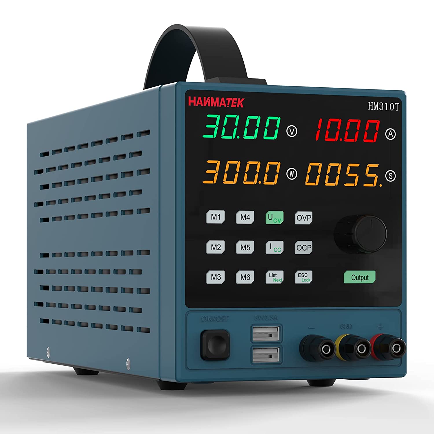
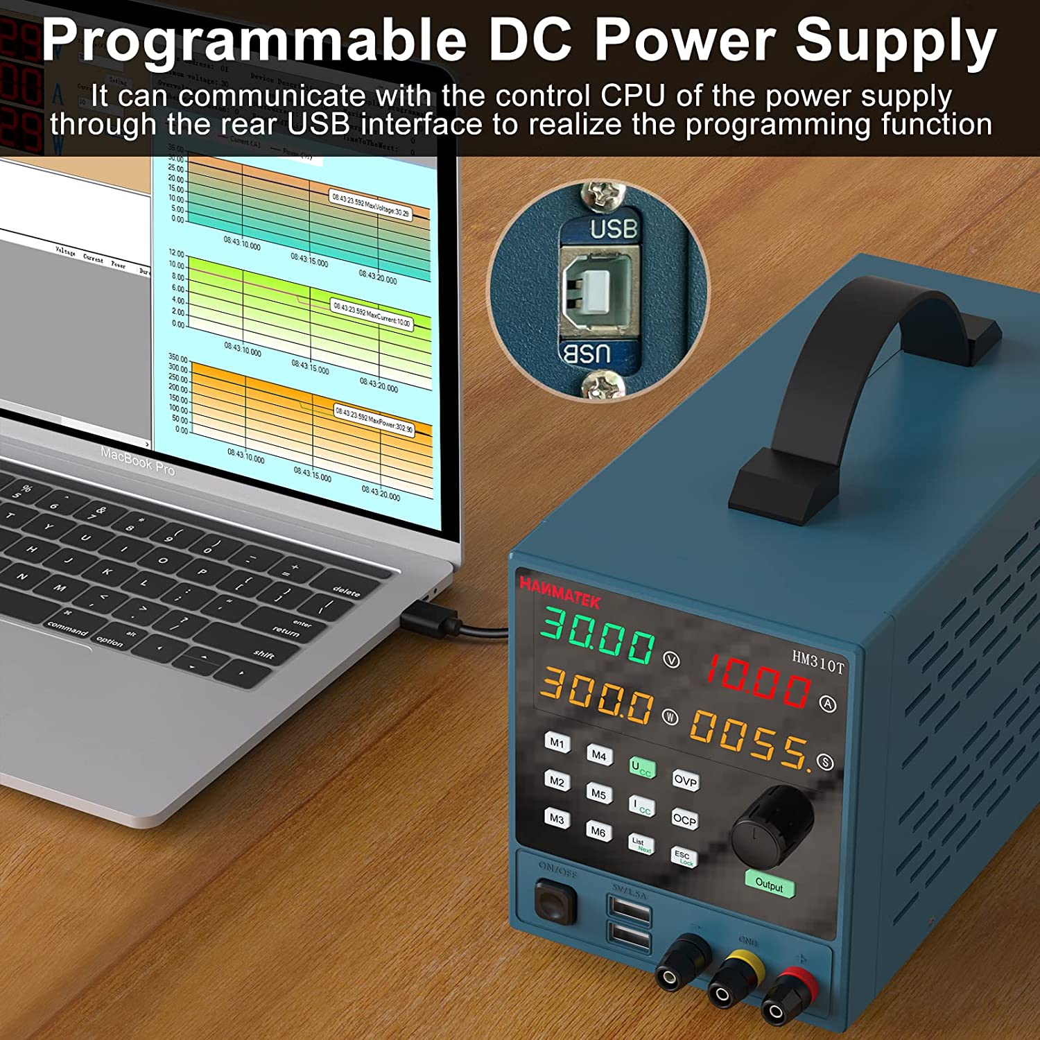
This repository contains a Python library to interact with the Hanmatek HM310T power supply over the Modbus interface.
Learn how this is accomplished for interacting with similar devices below in #further reading.
This library began as a flat prototype script (
pyHM310T.py). That original code is preserved on thelegacy/original-prototypebranch;mainis the packaged, pip-installable library.
⚠️ Safety Warning
The Hanmatek HM310T power supply is a device that can produce potentially dangerous levels of voltage and current. Always follow safety guidelines when working with electricity. Ensure your device is properly grounded and do not work on live circuits.
This software is provided "as is", without warranty of any kind, express or implied. Incorrect use of this software could lead to damage to your power supply or other equipment, or personal injury. Use this software responsibly and at your own risk.
⚠️ Use At Your Own Risk
By using this software, you agree that the authors and maintainers of this software are not liable for any damage to equipment, or any personal injury, that may occur through normal or abnormal use of this software. Always double-check your work and never leave a powered device unattended.
⚠️ AI-Assisted Code
Portions of this library were written with AI assistance and reviewed by multiple AI models and by human developers. That review does not guarantee correctness. Read the code and validate its behavior against your own hardware before relying on it — especially given the safety considerations above.
Requirements
- Python 3.10 or higher
- PyModbus 3.2.2 or newer, < 3.10 (3.2.2 was used for development; 3.10 renamed the
slave=keyword todevice_id=) - pyserial
- A Hanmatek HM310T power supply connected to a PC by USB
- May work with other Hanmatek or Modbus enabled power supplies, requires you to reverse engineer the unit. See further reading below for technical details and register values. Note that this library verifies it is talking to a genuine HM310T at connect time (registers
0x0003and0x0005) and refuses other models.
Installation
pip install hm310t
Or from source:
git clone https://github.com/joeyda3rd/hm310t.git
cd hm310t
pip install .
Usage
The API is property-based: setpoints and protection limits are plain attributes you read and assign; live readings and status come from small methods that return typed values.
from hm310t import PowerSupply

# port, baudrate=9600, slave=1, voltage_limit=30.0, current_limit=10.0
with PowerSupply(port="/dev/ttyUSB0") as psu:
    # Set protection trip points first, while the output is still off.
    psu.ovp = 6.0    # over-voltage protection, volts
    psu.ocp = 2.0    # over-current protection, amps
    psu.opp = 20.0   # over-power protection, watts

    # Setpoints the output will regulate to.
    psu.voltage = 5.0
    psu.current = 1.0
    print(f"Setpoint: {psu.voltage} V, {psu.current} A")

    # CAUTION: this energizes the terminals.
    psu.output_enabled = True
    print(f"Output enabled: {psu.output_enabled}")

    # One atomic read of the live output (reads ~0 with no load attached).
    m = psu.read_measurement()
    print(f"Measured: {m.voltage} V, {m.current} A, {m.power} W")

    # Protection status is a typed struct with a .tripped convenience flag.
    status = psu.read_protection_status()
    print(f"Tripped: {status.tripped}  ({status})")

    # Always disable the output when you are done -- closing does NOT do it.
    psu.output_enabled = False
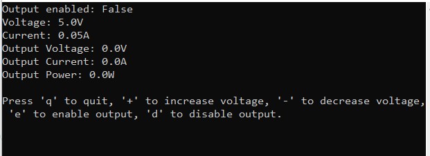
Runnable examples live in examples/: basic_usage.py (the script above, hardened) and tui_dashboard.py, a small curses dashboard.
API
Setpoints and protection limits are read/write properties (float unless noted):
| Property | Range | Description |
|---|---|---|
voltage |
0 – voltage_limit |
Output voltage setpoint (V) |
current |
0 – current_limit |
Output current setpoint (A) |
ovp |
0 – 30 | Over-voltage protection trip point (V) |
ocp |
0 – 10 | Over-current protection trip point (A) |
opp |
0 – 300 | Over-power protection trip point (W) |
output_enabled |
bool |
Output on/off. Assigning anything but a real bool raises TypeError |
comm_address |
1 – 250 (int) |
Modbus slave address; setting it retargets the connection |
voltage_limit, current_limit |
read-only | Software ceilings set in the constructor |
Methods:
| Method | Returns |
|---|---|
read_measurement() |
Measurement(voltage, current, power) — one atomic read of the live output |
read_protection_status() |
ProtectionStatus(is_ovp, is_ocp, is_opp, is_otp, is_scp) with a .tripped property |
read_raw_register(address) |
int — escape hatch to read any holding register directly |
close() |
Closes the serial connection (see "Known limitations") |
PowerSupply is a context manager (with PowerSupply(...) as psu:). Out-of-range setpoints raise OutOfRangeError; communication failures raise PowerSupplyCommunicationError; a non-HM310T device raises IncompatibleDeviceError. All derive from HM310TError.
Known limitations
- A clean close does not disable the output.
close()— and a normal exit from thewithblock — only closes the serial connection; the supply keeps sourcing at its setpoints. Leaving the output running is a legitimate bench workflow, so a clean close never forces it off. (Exception: if thewithblock exits because of an error,__exit__disables the output as a fail-safe.) Assignoutput_enabled = Falseexplicitly when you want it off. - HM310T only. The connect-time identity check (registers
0x0003= 3010 and0x0005= 0x0233) rejects other models in the family (e.g. the HM305), whose ratings or decimal scaling differ. - Multi-register writes use FC16. OPP and the 32-bit reads/writes use Modbus function code 16 (write-multiple-registers). The OEM doc claims only FC03/FC06 are supported, but FC16 is verified working on the real unit; a firmware that rejects it will raise rather than silently misbehave.
- Protection-status bits are not hardware-verified.
read_protection_status()decodes the OVP/OCP/OPP/OTP/SCP bits per the OEM doc and the original driver, but confirming each bit would require deliberately tripping each protection, which the suite does not do. Treat.trippedas advisory, not a safety interlock. - Not thread-safe. A
PowerSupplydrives a single serial handle with no internal locking; do not share one instance across threads without providing your own mutex.
Contributing
Contributions are welcome! Please open an issue if you encounter a bug or have a feature request. If you want to contribute code, please open a pull request.
License
This library is licensed under the MIT license.
Further Reading
When reverse engineering a power supply with a modbus interface, either over serial or other communication protocol, it's going to be essential to know the register addresses for the various I/O and the function code. In this case, we got lucky and the OEM provided that documentation, so we didn't need to fully reverse engineer it ourselves.
Without OEM docs, the general approach is to brute-force scan a wide address range (read, write a test value, read back) and/or sniff the unencrypted serial traffic of the OEM's own control software. This repo's own tools are narrower than that, since we didn't need a full discovery scan: tools/scan_registers.py is read-only and dumps only the 16 already-documented addresses (for spot-checking a suspect unit, not discovery). tools/characterize.py goes further -- it writes test values to confirm scaling and byte order, and sweeps the small 0x0000-0x0040 range to flag any undocumented responders -- but that's still a bounded sweep, not a 1-9999 scan. It's important to understand the Modbus protocol register addressing.
In the Modbus protocol, there are four types of data that can be accessed, each with its own address space:
- Coils (also known as Discrete Outputs): Addresses 00001 to 09999
- Discrete Inputs: Addresses 10001 to 19999
- Input Registers: Addresses 30001 to 39999
- Holding Registers: Addresses 40001 to 49999
Each of these address spaces can contain up to 10,000 addresses, for a total of 40,000 addresses. However, not all devices will use all of these addresses. The actual number of addresses used will depend on the specific device and its configuration.
It's also worth noting that in the Modbus protocol, addresses are often represented in a zero-based format. For example, the first holding register is often referred to as register 40001 in documentation, but in the actual Modbus messages, it would be referred to as holding register 0.
In this codebase specifically, every address you'll see -- in registers.py, the table below, or a raw pymodbus call -- is already the zero-based, function-code-relative form (e.g. 0x0010), never the 4xxxx-offset style some vendor docs use. You will not need to add or subtract an offset when reading this code.
In our case the entirety of the registers we accessed were in the holding registers space. The use of holding registers is common in Modbus devices, including power supplies, because holding registers can be read from and written to, making them versatile for various types of data. However, it's not guaranteed that every Modbus power supply will only use holding registers.
The specific Modbus registers used, and their purpose, can vary widely between different devices and manufacturers. Some devices might use input registers to provide read-only data, or coils and discrete inputs for binary data.
The best source of information about which registers are used by a particular device is the device's Modbus map or register map, which is usually provided in the device's documentation or manual. This map will list all the Modbus addresses used by the device, along with a description of the data stored at each address.
It's important to know what programming protocol and communication protocol are being used with your device as there are others besides Modbus or serial.
Documentation provided by the OEM (This was included on a CD provided by OEM)
The registers will accept read (03) and write (06) instructions -- and also FC16 (write-multiple-registers), despite the doc's cover page claiming otherwise. See "Known OEM documentation errors" below.
Register table (from the OEM doc, reconciled against hardware)
| Number | Function | Type | Decimal Places Capacity | Read/Write | Register Address |
|---|---|---|---|---|---|
| 0 | Output On/Off | Boolean | 0 | r,w | 0x0001 |
| 1 | Protect Status | Struct | 0 | r | 0x0002 |
| 2 | Specification | unsigned short | 0 | r | 0x0003 |
| 3 | Tail Classification | hexadecimal | 0 | r | 0x0004 |
| 4 | Decimal Point Values | hexadecimal | 0 | r | 0x0005 |
| 5 | Voltage Display Value | unsigned short | 2 | r | 0x0010 |
| 6 | Current Display Value | unsigned short | 3 | r | 0x0011 |
| 7 | Power Display Value | 2×16-bit, high word first | 3 | r | 0x0012,0x0013 |
| 9 | Set Voltage | unsigned short | 2 | r,w | 0x0030 |
| 10 | Set Current | unsigned short | 3 | r,w | 0x0031 |
| 12 | Set OVP | unsigned short | 2 | r,w | 0x0020 |
| 13 | Set OCP | unsigned short | 3 (#13) | r,w | 0x0021 |
| 14 | Set OPP | 2×16-bit, high word first | 2 | r,w | 0x0022,0x0023 |
| 15 | Set Comm Address | byte (1-250) | 0 | r,w | 0x9999 |
Register numbers 8 and 11 don't appear anywhere in the OEM doc -- not a transcription gap on our part. The doc's own footer note ("the red serial number part is public, the blue serial number part is programmable private, the black serial number part is optional") implies the vendor's internal numbering has entries this public doc doesn't disclose.
Notes
#1 Bit layout is below. Not independently hardware-verified -- confirming each bit would mean deliberately tripping each protection, which this project's test suite deliberately does not do. Treat .tripped as advisory, not a safety interlock (see "Known limitations" above).
#3 Semantics genuinely unknown -- the doc names the register but never explains what the value means. Still reachable via PowerSupply.read_raw_register(0x0004) if you ever want to poke at it.
#4 When it reads 0x0233: voltage 2 decimal places, current 3, power 3. Exact bit-packing, per the doc's own Note 2: (voltage_dp << 8) | (current_dp << 4) | (power_dp << 0). Checked at connect time in client.py's _check_decimal_capacity -- a device reporting anything else raises IncompatibleDeviceError rather than silently producing wrong values.
#7, #14 Two 16-bit registers combine into one 32-bit value, high word first (0x0012/0x0022 hold the high 16 bits, 0x0013/0x0023 the low). Confirmed both by the doc's own column labels and a hardware round-trip test (test_opp_uses_high_word_first_register_order).
#13 The table says 2 decimal places for OCP -- wrong. It's 3, matching CURRENT's convention, not OVP/voltage's. Confirmed against real hardware two ways: raw register 150 (intended as 1.50 A under a 2dp reading) displayed as 0.150 on the panel; and setting OCP to 2.010 from the panel round-tripped through the raw register as 2010, only consistent with 3dp (2010 / 1000 = 2.01; 2dp would give 20.1, nowhere close to what was dialed in). See "Known OEM documentation errors" below.
#14 Range 0-65535 (unsigned short) is suspect -- OPP is a 32-bit value across two registers, so a real range needs more than 16 bits. The power-display register (row 7, also 2 registers) has the identical 0-65535 range, suggesting this column was copy-pasted down rather than individually verified per row.
#15 Range is 1-250. client.py validates this as a plain Python int in that range (rejecting bool, floats, and anything outside 1-250) -- no separate typed representation needed.
// protection status bit

union _ST
{
  struct
  {
    uint8_t isOVP:1;//Over voltage protection
    uint8_t isOCP:1;//Over current protection
    uint8_t isOPP:1;//Over power protection
    uint8_t isOTP:1;//Over tempreture protection
    uint8_t isSCP:1;//short-circuit protection
  }OP;
  uint8_t Dat;
}
Known OEM documentation errors
OEM-docs/Modbus.pdf is the only register-level spec we have, but it contradicts itself in several places, confirmed by reading it closely and cross-checking against real hardware. Treat these as settled, not open questions:
- Supported function codes. Page 1: "this product just supports function codes: 03, 06." Page 3's own Table 8.1 lists function code 10 (write-multiple-registers, i.e. FC16) as a supported operation, and OPP/32-bit writes are verified working via FC16 against a real unit (see "Known limitations" above). The cover-page claim is wrong; trust Table 8.1 and the hardware.
- Slave address range. The general frame-structure intro (page 1) says the address range is "1 to 15 (decimal)." Section 1.1 "Address Code" (page 3) says "ranging from 1 to 250," matching the register table's own RS-Adder row ("1~250"). The code uses 1-250, matching the more specific, later section and the register's own documented range -- not the vague intro line.
- OCP decimal places. The register table lists OCP (0x0021) as 2 decimal places. Confirmed wrong against real hardware -- see note #13 above. It's 3, matching CURRENT's amperage-domain convention.
- OPP's "range" column (0-65535). OPP is a 32-bit value spanning two registers (0x0022 high, 0x0023 low), so a real range would need more than 16 bits. This looks copy-pasted from the single-register rows above it -- the power-display register (also 2 registers) has the identical suspect
0-65535range in row 7. - The page-5 worked example (function code 03 read) is internally inconsistent with the register table on the same page. It shows raw
0x01F4(500 decimal) at the current-display register as "5.00A" and raw0x3A98(15000 decimal) at the power-display register as "150.00W" -- both computed with 2 decimal places. But the table two pages earlier declares current and power display are 3 decimal places, which would give 0.500A and 15.000W instead. The example also treats power as a single 16-bit register, despite the table correctly noting it spans two (0x0012 high, 0x0013 low). The example section appears to be generic boilerplate the OEM didn't fully adapt for this product -- don't use it as a reference; use the register table plus Note 2's bit-packing formula for 0x0005 instead, both of which are internally consistent and match real hardware.
Takeaway: register addresses in the OEM doc are reliable (cross-checked against real hardware throughout this library's development), but decimal-place counts, ranges, and worked examples are not uniformly trustworthy -- verify against a real unit before depending on anything not already covered above.
Some previous work on the topic
http://www.roedan.com/controlling-a-cheap-usb-power-supply/
https://bitbucket.org/roedan/powersupply/src/master/
http://nightflyerfireworks.com/home/fun-with-cheap-programable-power-supplies
Release history Release notifications | RSS feed


Download files
Download the file for your platform. If you're not sure which to choose, learn more about installing packages.
Source Distribution
Built Distribution
Filter files by name, interpreter, ABI, and platform.
If you're not sure about the file name format, learn more about wheel file names.
Copy a direct link to the current filters
File details
Details for the file hm310t-0.1.2.tar.gz.
File metadata
- Download URL: hm310t-0.1.2.tar.gz
- Upload date:
- Size: 32.9 kB
- Tags: Source
- Uploaded using Trusted Publishing? No
- Uploaded via: twine/6.2.0 CPython/3.10.12
File hashes
| Algorithm | Hash digest | |
|---|---|---|
| SHA256 |
ea10e3a7d1d22df4f2b7c2c41f340fdbc70b5955523ceb52f521e07c202acc28
|
|
| MD5 |
0927dcf504295d7b1210b2030a31c418
|
|
| BLAKE2b-256 |
5879b8207fd335278974544c0c5898c6e08a75c88414e9c390d283899204284d
|
File details
Details for the file hm310t-0.1.2-py3-none-any.whl.
File metadata
- Download URL: hm310t-0.1.2-py3-none-any.whl
- Upload date:
- Size: 17.1 kB
- Tags: Python 3
- Uploaded using Trusted Publishing? No
- Uploaded via: twine/6.2.0 CPython/3.10.12
File hashes
| Algorithm | Hash digest | |
|---|---|---|
| SHA256 |
72a1760afad62310ad56b1abfa7098a146df87b902df3ba74575383154b8dc99
|
|
| MD5 |
7f5122edd510c44704c86a78d51003c3
|
|
| BLAKE2b-256 |
5d68ddb60b4d3f0d61fcfd9b14b7714802f0b687728cf14d39cb9c48acf09caf
|