mesh2cad


If you find this useful, you can support me by getting a SkinToScan pack, my other project. It's a one-time purchase that directly funds my open-source work.


Turn 3D meshes (STL/OBJ/PLY) into real, editable CAD (STEP): fitted planes, cylinders, spheres, cones, and constant-radius fillets instead of triangle soup. CLI + MCP server for AI agents. MIT, pure Python on top of OpenCascade.
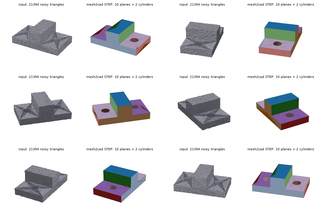
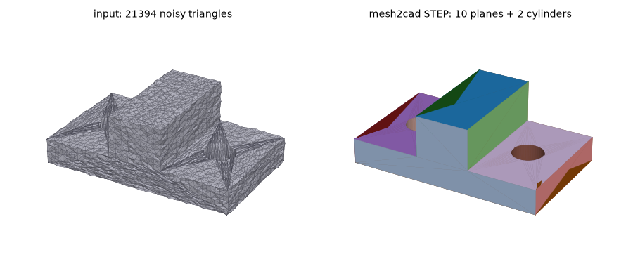
Left: 21k-triangle mesh with 0.1 mm noise. Right: the STEP mesh2cad writes: 10 planes + 2 cylinders, max deviation 0.05 mm from the true part.
Install
pip install mesh2cad              # CLI + STEP
pip install "mesh2cad[mcp]"       # + MCP server
pip install "mesh2cad[cadquery]"  # + run/verify generated CadQuery scripts
OpenSCAD scripts are plain text. Verifying one needs the openscad program (openscad.org); it is not a Python dependency. Without it the .scad file is still written.
Use
mesh2cad convert part.stl -o part.step --tol 0.1 --report report.md
mesh2cad report part.stl --json
--tol ≈ the noise / accuracy of your mesh in model units (default 0.1 % of the bounding-box diagonal).
Output: STEP + fidelity report: method (exact / faceted-hybrid / faceted), face types, solid validity, two-sided Hausdorff / RMS deviation, volume error, % area per surface type.
Editable parametric CadQuery script
For simple prismatic parts mesh2cad can also write a CadQuery Python script where every dimension is a named parameter, so you change a number and re-run instead of editing B-rep faces:
mesh2cad convert bracket.stl --cadquery bracket.py   # add -o bracket.step to also write STEP
python bracket.py                                    # -> bracket.step
# --- parameters ---
base_x           = 40.0  # base length (X)
base_y           = 30.0  # base width (Y)
base_t           = 6.0  # base thickness (Z)
...
hole_1_d         = 6.0  # diameter
hole_1_x         = 0.0
hole_1_y         = 0.0
hole_1_csk_d     = 12.0  # countersink diameter
hole_1_csk_angle = 90.0  # countersink angle
Make the hole 2 mm bigger: set hole_1_d = 8.0 and run it again. A plate or block whose four vertical corners share one radius also gets fillet_r and .edges("|Z").fillet(fillet_r), so the same edit grows the round.
A hole or boss on a side face uses the same kind of parameter. This is the block below (60×40×36, an Ø8 hole through X, an Ø6 hole 12 deep opening on +Y, an Ø10 boss 8 tall on +X):
boss_1_d     = 10.0  # diameter
boss_1_h     = 8.0  # height from the +X face
boss_1_y     = 10.0
boss_1_z     = 8.0
hole_1_d     = 8.0  # diameter (axis X)
hole_1_y     = 0.0
hole_1_z     = -6.0
hole_2_d     = 6.0  # diameter (axis Y)
hole_2_x     = -12.0
hole_2_z     = 8.0
hole_2_depth = 12.0  # blind depth from the +Y face
Set hole_1_d = 10.0 and run the script again. The volume drops by π(5²−4²)·60 mm³, the analytic change for that through hole.
A part that is one straight extrusion of a 2D outline is the same kind of script. An L, a notched plate, or a block with a slanted face, extruded along X, Y, or Z, becomes extrude_len plus an outline list. plug-aligner (the printed part in the table below, 7.3×17.7×5.5 mm) is a 5.5 mm extrusion along Z of an eight-point outline with a rectangular slot:
extrude_len = 5.5  # length along Z
extrude_0   = 0.0  # start along Z
# outline in the XY plane, (x, y)
outline = [
    (0.0, 0.0),
    (6.1, 0.0),
    (6.1, 6.95),
    (7.3, 6.95),
    (7.3, 10.75),
    (6.1, 10.75),
    (6.1, 17.7),
    (0.0, 17.7),
]
# through opening in the outline
cutout_1 = [
    (0.45, 1.85),
    (5.65, 1.85),
    (5.65, 15.85),
    (0.45, 15.85),
]
Set extrude_len = 7.5 and the part is 2 mm thicker. A corner moves when one pair in outline changes. A round through-hole on an extrusion is still hole_1_d, with hole_1_y and hole_1_z when the hole runs along X. cutout_1 is a polygonal slot that goes all the way through. An extrusion along Y stores the outline as (x, z); along X, as (y, z).
Supported: a Z-up box/plate base, rectangular pads on the top face, holes along X, Y, or Z (through, blind, countersunk when the axis is vertical, and counterbored on any of those axes), bosses along X, Y, or Z (straight, and drafted or chamfered when the axis is vertical), that one vertical corner radius, and one straight extrusion of a 2D outline along X, Y, or Z, including a polygonal through-slot and round through-holes. A counterbored hole is hole_N_d for the through diameter, hole_N_cbore_d for the large diameter, and hole_N_cbore_depth for how far that large diameter goes in from the face it opens on. A part that is a few of those extrusions is their intersection, or one of them minus straight cuts along the other axes. Two or three outlines use extrude_z_len / outline_z (and the same for X and Y); a single outline keeps extrude_len and outline. A cut is cut_1_len, cut_1_0, and cut_1. Up to four faces tilted to X, Y, and Z are planar clips (clip_1_x, clip_1_y, clip_1_z, clip_1_d). The box script is the one that is written when it already reproduces the mesh, so a plain plate stays base_x / base_y / base_t and does not become an outline list. A rectangular plate with a counterbored hole stays on those base parameters. Values are rounded to clean numbers (5.997 → 6.0) when that stays within --tol. Before writing, the script is executed and compared with the mesh (needs cadquery installed); if the part is outside this vocabulary or the script deviates, nothing is written and the command exits with code 2 and the reason. Use STEP output for everything else.
Editable parametric OpenSCAD script
The same parts can be written as OpenSCAD, which is what the 3D-printing Customizer on Thingiverse and Printables edits. Names and values match the CadQuery script. --openscad and --cadquery can be combined, and -o still writes STEP.
mesh2cad convert plate.stl --openscad plate.scad
openscad -o plate.stl plate.scad
A 40×30×6 plate with a Ø10 hole comes out as below, plus a short header. Before:
// --- parameters ---
/* [Base] */
// base length (X)
base_x   = 40.0;
// base width (Y)
base_y   = 30.0;
// base thickness (Z)
base_t   = 6.0;
base_cx  = 0.0;
base_cy  = 0.0;
// bottom face height
base_z0  = -3.0;

/* [Holes] */
// diameter
hole_1_d = 10.0; // [0.2:0.1:30]
hole_1_x = 0.0;
hole_1_y = 0.0;

/* [Hidden] */
$fn = 96; // circle segments

// --- model ---
module mesh2cad_part() {
  difference() {
    translate([base_cx, base_cy, base_z0 + base_t / 2])
      cube([base_x, base_y, base_t], center=true);
    translate([hole_1_x, hole_1_y, base_z0 - 1])
      cylinder(h=base_t + 2, d=hole_1_d);
  }
}

mesh2cad_part();
After, the hole is 2 mm bigger: one number changes, then re-render:
hole_1_d = 12.0; // [0.2:0.1:30]
Re-render (F6) and export STL. A drafted boss is a cylinder with r1/r2, a chamfer or countersink is the same, and the four vertical corners of a rectangular base are offset(r=fillet_r) on a smaller square, then extruded. A hole or boss whose axis is X or Y is the same cylinder, turned with rotate so it points along that axis; its parameters are the diameter and the two coordinates of the axis (hole_1_y / hole_1_z for an X hole). A straight extrusion is linear_extrude(extrude_len) of polygon(outline), with polygon(cutout_1) subtracted in 2D when the outline has a slot. An extrusion along Y or X is that solid turned so the outline sits in the XZ or YZ plane. A counterbored hole is a second cylinder of diameter hole_1_cbore_d and height hole_1_cbore_depth, from the face it opens on. Several extrusions are an intersection(), and a cut extrusion or a planar clip is subtracted. Names match the CadQuery script (extrude_len, outline, hole_1_d, hole_1_cbore_d, cut_1, clip_1_d). A slider (// [min:max]) is added only where the part gives a bound: hole diameter up to the shorter side of the face it is cut through (or of the outline, on an extrusion), counterbore diameter and depth on that same axis, fillet up to half the short side of the plate, draft until the tip would close, countersink angle in 60–120°, chamfer up to the boss, pad size up to the base, blind depth up to the length of the hole's axis. Positions (hole_1_x, base_z0, extrude_0, …) stay plain numbers. The outline is a point list, not a slider.
Same honesty as CadQuery. Before writing, mesh2cad renders the script with the openscad CLI and compares the STL to the mesh (sampled Hausdorff and volume, same limits as the CadQuery check). If openscad is not installed the file is still written and the command says it was unverified. If the part is outside this vocabulary, or the render does not match, nothing is written and the command exits with code 2 and the reason. Circles are $fn = 96 polygons; on these parts that is a few thousandths of a millimetre, not an analytic solid. STEP remains the path for everything else.
MCP server (Claude Desktop, Cursor, …)
{ "mcpServers": { "mesh2cad": { "command": "mesh2cad", "args": ["mcp"] } } }
Tools: convert(input_path, output_path?, tol?, cylinders?, spheres?, cones?), analyze(input_path, tol?, cylinders?, spheres?, cones?), report(input_path, tol?, cylinders?, spheres?, cones?), to_cadquery(input_path, output_path?, tol?), to_openscad(input_path, output_path?, tol?). Both script tools return the parameters and, when the script was run or rendered, the measured deviation. to_openscad also returns verified: false when the openscad program is absent. spheres and cones default on.
Listed on Glama and the TensorBlock MCP catalog.
How it works
- Load + clean mesh (trimesh). Noisy meshes get a Taubin-smoothed copy for normals. A clean CAD tessellation (dihedral angles piled onto a few exact values, including an export whose faces are single quads) is segmented on the raw normals, and a face of one or two triangles is kept.
- Region growing into planes; strip chains and leftovers are fitted as cylinders, spheres, or cones (normal-ray / algebraic / constant-normal-angle fits, robust nonlinear refinement). A narrow round between two planes is gathered back into one partial cylinder and snapped so its generators lie in those planes. A coaxial cylinder + cone component (countersink, chamfered pin) is split by normal-to-axis angle first. Small noisy patches that tile a sphere are merged into one spherical region. Split/redundant regions are merged and absorbed.
- Exact B-rep (OCP / OpenCascade): plane polygons from triple-plane intersections, circles from plane ∩ cylinder and plane ∩ sphere, plane ∩ cone, full cylindrical walls, partial fillet cylinders, spherical caps and zones, conical frustums, sewn into a solid and validated.
- Fallbacks: hybrid faceted solid (vertices snapped to fitted surfaces, coplanar triangles merged), then raw faceted solid.
- Fidelity report against the input mesh.
Self-test benchmark
Ground-truth cadquery parts → tessellated + subdivided (≤ 2 mm edges) → Gaussian vertex noise → mesh2cad → compared with the truth. 3 seeds, worst case shown (python benchmarks/run.py); the same cases run in CI. Numbers are STEP / B-rep fidelity (Hausdorff, RMS, volume, face counts). Parametric OpenSCAD and CadQuery export are verified separately when you pass --openscad / --cadquery (or the MCP to_openscad / to_cadquery tools); they are not rows in this table.
| part | noise σ (mm) | exact | faces (plane/cyl[/sph[/cone]]) | radius err (mm) | Hausdorff (mm) | RMS (mm) | vol err % | time s |
|---|---|---|---|---|---|---|---|---|
| cube | 0.0 | 3/3 | 6/0 | - | 0.000 | 0.000 | 0.00 | 0.6 |
| cube | 0.05 | 3/3 | 6/0 | - | 0.019 | 0.006 | 0.07 | 0.6 |
| cube | 0.2 | 3/3 | 6/0 | - | 0.075 | 0.026 | 0.34 | 0.7 |
| l_bracket | 0.0 | 3/3 | 8/0 | - | 0.000 | 0.000 | 0.00 | 0.9 |
| l_bracket | 0.05 | 3/3 | 8/0 | - | 0.040 | 0.006 | 0.03 | 1.1 |
| l_bracket | 0.2 | 3/3 | 8/0 | - | 0.216 | 0.026 | 0.15 | 1.2 |
| stepped_block | 0.0 | 3/3 | 11/0 | - | 0.000 | 0.000 | 0.00 | 1.0 |
| stepped_block | 0.05 | 3/3 | 11/0 | - | 0.032 | 0.006 | 0.02 | 2.2 |
| stepped_block | 0.2 | 3/3 | 11/0 | - | 0.136 | 0.022 | 0.07 | 2.4 |
| plate_with_hole | 0.0 | 3/3 | 6/1 | - | 0.016 | 0.002 | 0.00 | 1.8 |
| plate_with_hole | 0.05 | 3/3 | 6/1 | - | 0.028 | 0.006 | 0.05 | 2.3 |
| plate_with_hole | 0.2 | 3/3 | 6/1 | - | 0.078 | 0.023 | 0.18 | 1.9 |
| boss | 0.0 | 3/3 | 7/1 | - | 0.027 | 0.006 | 0.01 | 1.8 |
| boss | 0.05 | 3/3 | 7/1 | - | 0.033 | 0.007 | 0.03 | 2.2 |
| boss | 0.2 | 3/3 | 7/1 | - | 0.091 | 0.017 | 0.09 | 4.6 |
| ribbed_plate | 0.0 | 3/3 | 10/2 | - | 0.012 | 0.001 | 0.00 | 2.5 |
| ribbed_plate | 0.05 | 3/3 | 10/2 | - | 0.028 | 0.005 | 0.03 | 2.5 |
| ribbed_plate | 0.2 | 3/3 | 10/2 | - | 0.108 | 0.020 | 0.12 | 2.6 |
| spherical_dome | 0.0 | 3/3 | 6/0/1 | - | 0.065 | 0.007 | 0.04 | 1.8 |
| spherical_dome | 0.05 | 3/3 | 6/0/1 | - | 0.067 | 0.008 | 0.06 | 1.8 |
| spherical_dome | 0.2 | 3/3 | 6/0/1 | - | 0.241 | 0.028 | 0.25 | 1.9 |
| spherical_pocket | 0.0 | 3/3 | 6/0/1 | - | 0.046 | 0.004 | 0.02 | 2.2 |
| spherical_pocket | 0.05 | 3/3 | 6/0/1 | - | 0.057 | 0.005 | 0.03 | 2.1 |
| spherical_pocket | 0.2 | 3/3 | 6/0/1 | - | 0.075 | 0.015 | 0.13 | 2.1 |
| countersunk_plate | 0.0 | 3/3 | 6/1/0/1 | - | 0.039 | 0.003 | 0.01 | 2.2 |
| countersunk_plate | 0.05 | 3/3 | 6/1/0/1 | - | 0.055 | 0.009 | 0.07 | 2.2 |
| countersunk_plate | 0.2 | 1/3 | 16342/0, 6/1/0/1 | - | 0.590 | 0.049 | 0.54 | 21.2 |
| tapered_boss | 0.0 | 3/3 | 7/0/0/1 | - | 0.086 | 0.011 | 0.05 | 1.9 |
| tapered_boss | 0.05 | 3/3 | 7/0/0/1 | - | 0.095 | 0.012 | 0.05 | 1.8 |
| tapered_boss | 0.2 | 3/3 | 7/0/0/1 | - | 0.123 | 0.025 | 0.22 | 2.1 |
| chamfered_boss | 0.0 | 3/3 | 7/1/0/1 | - | 0.053 | 0.005 | 0.02 | 2.7 |
| chamfered_boss | 0.05 | 3/3 | 7/1/0/1 | - | 0.096 | 0.012 | 0.08 | 2.5 |
| chamfered_boss | 0.2 | 3/3 | 7/1/0/1 | - | 0.511 | 0.059 | 0.49 | 2.3 |
| filleted_plate | 0.0 | 3/3 | 6/4 | 0.001 | 0.013 | 0.002 | 0.01 | 1.3 |
| filleted_plate | 0.05 | 3/3 | 6/4 | 0.100 | 0.038 | 0.008 | 0.07 | 1.3 |
| filleted_plate | 0.2 | 2/3 | 5796/0, 6/4, 7/3 | 0.447 | 0.857 | 0.086 | 0.33 | 6.8 |
| filleted_box | 0.0 | 3/3 | 6/4 | 0.003 | 0.006 | 0.001 | 0.00 | 1.8 |
| filleted_box | 0.05 | 3/3 | 6/4 | 0.041 | 0.028 | 0.006 | 0.03 | 1.9 |
| filleted_box | 0.2 | 3/3 | 6/3, 6/4 | 0.206 | 0.845 | 0.048 | 0.18 | 1.8 |
| filleted_bracket | 0.0 | 3/3 | 8/6 | 0.005 | 0.010 | 0.002 | 0.00 | 1.8 |
| filleted_bracket | 0.05 | 3/3 | 8/6 | 0.131 | 0.041 | 0.008 | 0.02 | 1.9 |
| filleted_bracket | 0.2 | 0/3 | 10452/0 | - | 0.958 | 0.130 | 0.50 | 13.7 |
"exact" = valid analytic B-rep. A face count equal to the triangle count is the faceted fallback, which is still a valid solid. radius err is the worst |fitted − true| cylinder radius among seeds that came back exact, and - when the part has no fillet radius or no seed was exact. All rows are the worst of 3 seeds from python benchmarks/run.py. The 90° countersink (Ø6 hole, Ø12 head, 3 mm deep) at 0.2 mm noise is exact on 1 of 3 seeds. At 0.2 mm the filleted bracket falls back on every seed; the plate is exact on 2 of 3, and one of those solids is missing a corner (7 planes + 3 cylinders). The block stays a valid solid, but one seed keeps only three of the four rounds (Hausdorff 0.85 mm). CI checks the cases that are exact, plus fallbacks that must stay valid solids.
Real parts
The table above subdivides every edge to ≤ 2 mm, so a planar face is many triangles. An STL written by a CAD tool is the other way around: long triangles, very uneven size, no noise. python benchmarks/real_parts.py downloads six printed parts from the Original Prusa i3 MK3S, converts them at the default tolerance, and tries --cadquery and --openscad on each. The files are Prusa Research's, GPL-2.0, from prusa3d/Original-Prusa-i3 at commit 529e5ad (Printed-Parts/STL/<name>.stl). They are cached under benchmarks/.cache and are not part of this repository. CI does not run the script (it needs the network). A coarse, unsubdivided cadquery mesh of the same kind is what tests/test_coarse.py checks.
| part | triangles | method | output faces | regions | valid | Hausdorff | RMS | vol err % | time s |
|---|---|---|---|---|---|---|---|---|---|
| plug-aligner | 48 | exact | 14 plane | 14 plane | yes | 0.0000 | 0.0000 | 0.000 | 0.6 |
| endstop-block | 308 | exact | 15 plane, 2 cylinder | 15 plane, 2 cylinder | yes | 0.0168 | 0.0036 | 0.204 | 2.0 |
| y-belt-idler | 2464 | faceted-hybrid | 2464 plane | 60 plane, 15 cylinder, 1 sphere, 5 faceted | yes | 0.2797 | 0.0083 | 0.019 | 12.3 |
| y-belt-holder | 2472 | faceted | 890 plane | 56 plane, 6 cylinder, 2 sphere, 1 cone, 8 faceted | yes | 0.0000 | 0.0000 | 0.001 | 21.0 |
| y-motor-holder | 2802 | faceted-hybrid | 2802 plane | 60 plane, 21 cylinder, 7 faceted | yes | 0.2738 | 0.0231 | 0.185 | 13.4 |
| y-rod-holder | 5608 | faceted | 3043 plane | 57 plane, 4 cylinder, 4 sphere, 3 cone, 5 faceted | yes | 0.0000 | 0.0000 | 0.001 | 38.6 |
plug-aligner is a 14-plane prism, 48 triangles, watertight. It comes back exact: 14 planes, Hausdorff 0, 0.6 s. endstop-block (308 triangles, 13.6×9×14 mm) is exact: 15 planes and two cylinders, radii 1.65 mm and 3.10 mm, in 2.0 s. Hausdorff 0.017 mm and volume error 0.20% are the chordal error of those holes against the triangles. On 0.7.0 both were faceted-hybrid. The aligner was one unfitted region (the output happened to be 14 planes only after the faceted merge). The endstop was 75 planar faces, holes included, in about 4 s.
The other four are valid solids and finish in 12–39 s. They are not exact. Each keeps regions that are not a plane, cylinder, sphere, cone, or a fillet between two planes: small edge rounds and belt-profile patches. Unfitted area is 0.5% on the idler, 1.8% on the holder, 1.0% on the motor holder and 6.6% on the rod holder. Exact sewing needs every region fitted, so these fall back. faceted-hybrid snaps vertices onto the surfaces that did fit. On the idler the Hausdorff is 0.28 mm and the RMS is 0.008 mm, so the miss is local; the output is still one face per triangle. faceted is the raw mesh (Hausdorff 0) with coplanar triangles merged: the holder goes from 2472 triangles to 890 faces, the rod holder from 5608 to 3043. Cylinders of one radius stay split where a groove breaks the wall. On the idler the R=11.1 mm round is eight separate bands, with other cylinders at 10.11, 2.8, 1.65 and 1.6 mm, not one face. The motor holder's large round comes back as several close radii (about 8.6, 8.9 and 9.1 mm) rather than one cylinder or cone.
--cadquery and --openscad write plug-aligner and endstop-block. plug-aligner is the extrusion above, and both scripts match the mesh to 0.0000 mm. endstop-block is not one extrusion: the cross-section changes along the part. The script is the intersection of three silhouettes (extrude_z_len 14 mm from z=−15 (outline_z, eight points), extrude_x_len 13.56 mm from x=−13 (outline_x, five points), extrude_y_len 9 mm from y=−16 (outline_y, five points)), plus an Ø3.3 hole along X at y=−11, z=−11 with an Ø6.2 counterbore 8 mm deep from the −X end (hole_1_d, hole_1_cbore_d, hole_1_cbore_depth), plus one planar clip (clip_1_x 0.5, clip_1_y −0.7071, clip_1_z 0.5, clip_1_d 7.0561). Both self-checks are 0.0421 mm. The limit at the default tolerance is max(4·tol, 0.1) = 0.1 mm. The CadQuery volume error against the mesh is 0.109%. The other four are refused with "part has unfitted (faceted) regions". python benchmarks/real_parts.py prints:
| part | cadquery | dev mm | openscad | dev mm |
|---|---|---|---|---|
| plug-aligner | yes | 0.0000 | yes | 0.0000 |
| endstop-block | yes | 0.0421 | yes | 0.0421 |
| y-belt-idler | no | - | no | - |
| y-belt-holder | no | - | no | - |
| y-motor-holder | no | - | no | - |
| y-rod-holder | no | - | no | - |
On 0.7.0 the idler was faceted, 915 faces, about 15 s. The holder, motor holder and rod holder did not finish within 300 s. Segmentation of those meshes was a few seconds. The time was UnifySameDomain on the faceted fallback, after the fit had left the solid as one unfitted component, and that call hit its timeout. Fitting the planes and cylinders keeps the aligner and the endstop off that path. The four that still fall back now finish in under a minute.
Limits (v0.10.0)
Planes, cylinders, spheres, cones, and constant-radius fillets between two planes. Cylinders must end on planes perpendicular to their axis (through-holes, bosses, pins). Spheres are exact when each boundary loop is a single plane ∩ sphere circle (domes, spherical bosses, spherical pockets, and zones between two parallel planes). A sphere that runs into an edge or a cylinder falls back to the hybrid solid; vertices are still snapped onto the fitted sphere, but the face stays faceted. Cones are exact when they run between two planes perpendicular to their axis: countersinks, chamfered holes and bosses, drafted/tapered bosses. Cones may also meet a coaxial cylinder (countersunk hole, chamfered pin). A cone that ends in its apex falls back to the hybrid solid. Countersinks and narrow chamfers are exact through about 0.05 mm of noise; a 2 mm chamfer and a wide drafted wall stay exact at 0.2 mm. The countersunk plate's 90° countersink (Ø6 hole, Ø12 head, 3 mm deep) at 0.2 mm noise is exact on one of three seeds. On the other two the conical band and the hole wall meet at a single vertex, so those seeds fall back to a valid faceted solid.
A fillet between two planes is a partial cylinder. When the round runs from one cap to another (rounded vertical corners of a plate or block, a single edge, the inner corner of an L as well as the outer ones), it comes back as one cylinder, tangent to both walls, with the radius in the report's cylinder faces. The radius is the one whose axis is tangent to both walls and which fits the arc; wall triangles that remain in the patch do not pull it off. On the synthetic plate (r=5 mm), block (r=2 mm) and L-bracket (r=3 mm) that rebuild is exact at 0 and 0.05 mm of noise, all three seeds. With no noise the radius error is 0.001 mm on the plate, 0.003 mm on the block and 0.005 mm on the bracket. At 0.05 mm the worst radius error is 0.041 mm on the r=2 corners, 0.100 mm on the r=5 plate and 0.131 mm on the r=3 bracket. At 0.2 mm the bracket falls back on every seed. The plate is exact on 2 of 3 seeds, and one of those solids is missing a corner. The block is a valid solid on every seed, but one seed keeps only three of the four rounds and the Hausdorff rises to 0.85 mm. Whatever does not sew stays a valid faceted solid.
A fillet that runs into a spherical corner (every edge of a box filleted) is not rebuilt: the corner is a sphere octant bounded by three cylinders. A fillet between a plane and a coaxial cylinder (the base of a boss, the rim of a hole) is a torus, and is not rebuilt either. Free-form surfaces are still unsupported. CadQuery and OpenSCAD export write fillet_r only for the four vertical corners of a rectangular base (OpenSCAD as offset(r=fillet_r) on the base profile). An L-bracket fillet, a spherical corner, and a torus stay on the STEP path.
The parametric scripts are one Z-up box, pads on its top face, and holes and straight cylindrical bosses whose axis is X, Y, or Z. A through hole runs from one face of the base to the opposite face. A blind hole opens on one face; hole_N_depth is the distance from that face to the flat end. A side boss sits on one side face and grows straight out. Countersinks, drafts, and chamfers are still vertical only. An axis that is not aligned with X, Y, or Z is refused, and so is a side feature that does not open on a face of the base.
A straight extrusion of one outline is written as well, along X, Y, or Z. The outline may be an L, a notch, or a slanted edge. extrude_len is the length, extrude_0 is where it starts, and outline is the point list (YZ when the extrusion is along X, XZ along Y, XY along Z). A polygonal opening through that extrusion is cutout_N. A round through-hole keeps hole_N_d and its position. A counterbored through-hole adds hole_N_cbore_d and hole_N_cbore_depth. When the box script already matches the mesh it is the one that is written, so a plate, a pad, and a side hole stay on base_x, hole_1_d, and fillet_r.
A part made of a few of those extrusions is written too, when every region is a plane or an axis-aligned cylinder. The solid is the intersection of the silhouettes along X, Y, and Z, or one of those extrusions minus straight cut extrusions along the other axes. A single outline keeps the names above. Two or three use extrude_z_len / outline_z and the same for X and Y. A cut is cut_1, cut_1_len, and cut_1_0. A face tilted to all three axes, at most four of them, is a planar clip: clip_1_x, clip_1_y, clip_1_z, clip_1_d with the outward normal and n·x = d. Intersected extrusions overlap by 0.02 mm in the script so the shared end faces stay a manifold; the other outline stops at the true end, so the nominal solid does not grow. endstop-block is this case (three silhouettes, one counterbored hole, one clip), and both scripts deviate from the mesh by 0.0421 mm.
Still refused, and the command says which: a boss on an extruded outline; a countersink, chamfer, or draft on an extrusion (those stay vertical, and only on the box vocabulary); a rounded edge that is not the four vertical corners of a rectangular base; a hole that does not pass through; a stepped hole that is not a counterbored through-hole; more than four faces tilted to X, Y, and Z; a recess that is not a straight cut along X, Y, or Z; a sphere; an unfitted region. A flat patch that the fitter returned as a sphere is written as the plane its vertices lie on, so a noisy counterbore floor is not refused as a sphere. y-belt-idler, y-belt-holder, y-motor-holder, and y-rod-holder are still refused with "part has unfitted (faceted) regions". Free-form surfaces stay on the STEP path.
On the 60×40×36 block (Ø8 through hole along X at y=0, z=−6; Ø6 blind hole, 12 deep, opening on +Y at x=−12, z=8; Ø10 boss, 8 tall, on +X at y=10, z=8) both scripts recover those dimensions with no noise and at 0.05 mm noise. With no noise the CadQuery script matches the mesh to 0.006 mm (volume error 0.004%) and the OpenSCAD script to 0.006 mm (volume error 0.003%). At 0.05 mm noise the check against that noisy mesh is 0.139 mm / 0.015% for CadQuery and 0.149 mm / 0.016% for OpenSCAD, under the same limit as every other script, max(4·tol, 0.1) = 0.20 mm. The blind end is not its own plane on this part (the disk stays in the cylinder region), so the depth is the median of the vertices clustered at that end. The exact STEP builder does not sew that cylinder; STEP export of this block falls back to a valid faceted solid, Hausdorff 0.004 mm from the mesh. Anything else outside this vocabulary stays on the STEP path.
Development
pip install -e .[dev]
pytest
python benchmarks/real_parts.py   # Prusa STLs, needs the network; not in CI
python docs/make_demo.py   # regenerate images (needs matplotlib, pillow)
License: MIT
1 maintainer

Metadata
1 maintainer
Release files for mesh2cad 0.10.0
For a detailed explanation of source distributions (sdists) and built distributions (wheels), please see the package formats documentation.
Source distribution (sdist)
| File | Size | Uploaded | Provenance | |
|---|---|---|---|---|
| mesh2cad-0.10.0.tar.gz | 870.8 kB | With provenance | Details |
Built distribution (wheel)
| File | Interpreter | ABI | Platform | Reset |
|---|---|---|---|---|
| mesh2cad-0.10.0-py3-none-any.whl | Python 3 | none | any | Details |
Total release size: 968.4 kB
Release files / mesh2cad-0.10.0.tar.gz
| Download URL | mesh2cad-0.10.0.tar.gz |
|---|---|
| Size | 870.8 kB |
| Tags | Source |
|
SHA-256 checksum How to use checksums |
1b76adc8b6f68dc5b4dc46351d5b1958eb24420e921d498884862364da4cb5db
|
|
BLAKE2b-256 checksum How to use checksums |
0c752dd34e30fd118d7d6e8b3e2089feaa104aec63ca14ae47789287a682696e
|
| Upload date | |
|
Uploaded using Trusted Publishing? What is trusted publishing? |
Yes |
| Uploaded via |
twine/7.0.0 CPython/3.13.16
|
Provenance
Provenance describes where a file came from. On PyPI, provenance is shared via attestations, which provide a verifiable record of the build or publishing details. View details, limitations and caveats.


PyPI Publish Attestation
PyPI verified that this artifact, at this checksum, originated from the publisher listed below.
Signed by GitHub Actions, verified by PyPI on Oct 21, 2026.
Transparency logRelease files / mesh2cad-0.10.0-py3-none-any.whl
| Download URL | mesh2cad-0.10.0-py3-none-any.whl |
|---|---|
| Size | 97.6 kB |
| Tags | Python 3 |
|
SHA-256 checksum How to use checksums |
776d02ad95b7f2de37ebe859cebe985a3aae589515f5586ea427c57891424bec
|
|
BLAKE2b-256 checksum How to use checksums |
78598844dae8a7695cde4a3fa9922a1810cabd748041cf293725a9f3051298c8
|
| Upload date | |
|
Uploaded using Trusted Publishing? What is trusted publishing? |
Yes |
| Uploaded via |
twine/7.0.0 CPython/3.13.16
|
Provenance
Provenance describes where a file came from. On PyPI, provenance is shared via attestations, which provide a verifiable record of the build or publishing details. View details, limitations and caveats.
PyPI Publish Attestation
PyPI verified that this artifact, at this checksum, originated from the publisher listed below.
Signed by GitHub Actions, verified by PyPI on Oct 21, 2026.
Transparency logSecurity for mesh2cad 0.10.0
Provenance
Provenance describes where a file came from. On PyPI, provenance is shared via attestations, which provide a verifiable record of the build or publishing details. View details, limitations and caveats.
Full provenance
All 2 files in this release have been uploaded with provenance metadata.
Attestation for mesh2cad-0.10.0.tar.gz
PyPI Publish Attestation
PyPI verified that this artifact, at this checksum, originated from the publisher listed below.
Signed by GitHub Actions, verified by PyPI on Oct 21, 2026.
Transparency logA note on package security
PyPI is a repository for distributing packages, not a service for auditing them. While third-party security researchers and our staff do their best to detect and remove malicious packages, PyPI cannot guarantee the quality, security or suitability of any given package.
To learn more about protecting yourself from malicious actors, visit our package security documentation.